


I recently returned from Mobile, Ala., where I spent a full week at the Teledyne Continental Motors factory going through TCM’s Aviation Technician Advanced Training Program (ATATP). I attended the course with AVweb Executive Editor Jeb Burnside (who owns a TCM-powered C33A Debonair) and my good friend Chris Wrather (who owns a TCM-powered V35 Bonanza). All three of us are very maintenance-involved aircraft owners — Chris and I do virtually all the maintenance on our respective airplanes, and Jeb does a lot of the work on his — and all of us found the program to be a fascinating and highly educational week of total immersion into TCM piston aircraft engines.
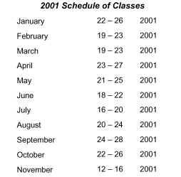
The course is held during the last full week of every month at the factory — located at Mobile Downtown Airport — and tuition is $750 for the week. Program details and enrollment instructions can be found on the TCM Link Web site. (You might want to bookmark this URL, since it’s not particularly easy to find from the TCM Link home page.)
I’m Not An A&P (But I Play One On The Internet)
 Although TCM designed the ATATP syllabus primarily for professional aviation maintenance technicians, they encourage maintenance-involved aircraft owners like Jeb and me to attend. (Chris actually holds an A&P certificate, but we try not to hold that against him.)
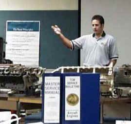
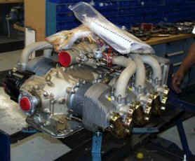
Participants spend a full week being taught by TCM subject matter experts, surrounded by disassembled engines, components and cutaways. Mornings are devoted to classroom discussion, while afternoons are mostly spent performing hands-on activities ranging from changing cylinders to adjusting fuel injection systems to setting magneto e-gap.
The classes are small — limited to about 15 students — providing plenty of opportunity for Q&A with the TCM instructors, as well as exploration of off-syllabus subjects. A great advantage of holding the course at the factory is that all the technical resources of TCM are near at hand. If a question comes up in class that the instructors can’t answer, they have ready access to the appropriate expert, and generally come back with a definitive answer after lunch or the next day.
As a an active wrench swinger, writer of maintenance-oriented articles, and member of the technical staff at Cessna Pilots Association, I arrived in Mobile knowing a fair bit more about TCM engines than your average A&P, so I had modest expectations for what I would derive from the class. However, I must say that I was pleasantly surprised, and came away learning a good deal more than I anticipated. All in all, it was a terrific week, extremely worthwhile and highly recommended.
Welcome to Mobile
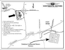
![Mobile Downtown Airport [BKF]](https://s30121.pcdn.co/wp-content/uploads/2019/06/tcmatatp_airport_diagram_small-2.gif) Chris and I flew from California to Alabama in my Cessna 310, arriving at Mobile Downtown Airport [BFM] on Sunday afternoon. The former Brookley AFB is now Mobile’s GA reliever and home to the TCM factory (see diagram). Jeb, who’d flown commercially to Mobile International [MOB] because his Debonair was in the avionics shop, was there to meet us in a rental car. After transferring our bags from the 310 to the car, the three of us headed for the hotel.
Chris and I flew from California to Alabama in my Cessna 310, arriving at Mobile Downtown Airport [BFM] on Sunday afternoon. The former Brookley AFB is now Mobile’s GA reliever and home to the TCM factory (see diagram). Jeb, who’d flown commercially to Mobile International [MOB] because his Debonair was in the avionics shop, was there to meet us in a rental car. After transferring our bags from the 310 to the car, the three of us headed for the hotel.
In addition to the $750 course tuition, students attending the ATAP are responsible for transportation and lodging costs. TCM has made hotel arrangements with the TownePlace Suites at an astonishingly low room rate: $40 per night. TownePlace is an attractive hotel located about halfway between MOB and BFM airports, specializing in extended-stay business travelers. Chris, Jeb and I all found the accommodations there to be more than adequate, and the price unbeatable. A rental car is a must, however, since it’s roughly a 15-minute freeway drive from the hotel to the TCM factory (which is located on-airport at BFM).
 After checking into the hotel, the first order of business was to find a place for dinner. For a small city, Mobile has a remarkable variety of places to eat. The emphasis seems to be on fresh seafood and New Orleans-style cuisine, and we chose the Original Oyster House on Mobile Bay for our arrival night dinner. But you can pretty much find any sort of food that strikes your fancy — we had marvelous steaks one evening at Ruth’s Chris, for example, and some interesting Nouvelle Mexican cuisine another. In the interests of time, catered lunches are provided by TCM each day of class, and consumed in the classroom. Suffice it to say that none of us lost weight during our week in Mobile.
The course was sufficiently intensive that none of us mustered the energy to check out the nightlife during our weeklong stay in Mobile. The locals assured us that there was plenty to be had, including riverboat gambling in nearby Biloxi, Miss. We decided to take their word for it, and our late-night prowls were pretty much limited to the Krispy Kreme doughnut shop near our hotel.
Let’s Get Started
 Bright and early at 7:30 a.m., we met up at the rental car to head for our first day of training. About 20 minutes later (after missing our off-ramp and having to double back), we arrived at the TCM factory, parked in the small visitors parking area just outside the main entrance to the plant, and signed in at the guard building. A friendly (but well-armed) security guard directed us to the classroom facility, located in an undistinguished industrial-looking building adjacent to the factory. Fortunately, we’d allowed some extra time for getting lost, so we didn’t embarrass ourselves by arriving late. Class begins each day at 8:00 a.m. and runs until 4:30 p.m.
The first session started off with some introductions of both instructors and students. Class size is limited to approximately 15 students, and our class was full (as is usually the case). Most of the attendees were full-time professional AMTs attending the course at their employer’s expense. Some had traveled a long way to attend, with the hands-down prizewinner being a delightful fellow from a GA maintenance facility in Finland. Also participating as students were a couple of TCM employees, including a production test cell technician and a specialist from the marketing department. Together with we three amateur wrench swingers, it was a rather diverse and interesting group.
 Five TCM instructors participated in our seminar:
Billy Beam, lead ATATP instructor, nine years with TCM, prior to which he owned an overhaul shop for five years.
Bob Robbins, founder of ATATP and longtime TCM engineer.
Don Fitzgerald, former ATATP lead instructor, now works for TCM marketing and in charge of the TCM Link program. Don taught the fuel injection system segment of the course.
Tim Davis, head of tech support for TCM’s ignition systems division (formerly Bendix/Scintilla), who taught the ignition systems segment.
Pat Pierce, long-timer in manufacturing at TCM, who conducted the factory tour segment.
All were very knowledgeable and personable instructors, and all were extremely well-prepared. I was impressed that each instructor made a point of giving us their email addresses and telephone extensions, inviting us to contact them directly should we have any questions after the course was over.
Training Materials: Worth The Price of Admission
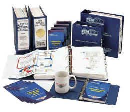 The next order of business was a quick overview of the course organization and a walk-through of the training materials furnished by TCM to each ATATP student. The training materials are extensive — most of our group agreed they alone were worth the $750 tuition — and their sheer weight and volume caused many of us to express concern about how we would manage to get them home after the course was over. Billy Beam anticipated our concern, and quickly assured us that TCM would arrange to pack and ship the materials to us at the end of the class.
Most of the course materials were organized into three mammoth 8.5×11-inch loose-leaf binders. The first of these is the ATATP Training Manual, containing detailed study text for each technical topic covered by the course, more than 90 11×17-inch foldout diagrams (many in color), and a workbook section containing a series of study questions. (While there are no formal exams or quizzes during the course, instructors would often pose questions from the workbook to check our comprehension and see if any subjects needed repeating.) Also included in the Training Manual are model-by-model engine installation procedures, a detailed discussion of what should be covered during 100-hour/annual inspections, and an assortment of reprinted technical briefs from various engine component vendors, including a particularly fascinating one from Glacier Vendervell on bearing failure analysis.
The second binder contains a complete compendium of all TCM aircraft engine service bulletins filed in reverse chronological order (newest first), together with a very useful set of cross-reference indexes that make it easy to locate the service bulletins that relate to any particular subject. We found ourselves referring to this binder frequently throughout the course.
The third binder contains the TCM Ignition Systems Master Service Manual, including overhaul manuals, illustrated parts lists, service bulletins and application data for all TCM/Bendix magnetos, harnesses, ignition switches and starting vibrators. This was the "bible" for the fourth day of the course, which was devoted to the care and feeding of Bendix mags and related ignition components.
In addition to these three big loose-leaf binders, we also received a compact binder containing a series of handy "ready reference guides" covering TCM engine specifications, torque specifications, fuel injection system adjustment and cylinder installation. Two videos are also furnished: one covering cylinder removal/replacement and the other fuel injection system adjustment. Also provided are a TCM Link CD-ROM, an assortment of TCM decals, and — perhaps the most heavily used of all during the course — an official TCM-logo coffee mug.
TCM Engines, Then…
Before getting into the meat and potatoes of the current TCM engine product line, instructor Billy Beam provided a brief but fascinating history of the company. Continental, we learned, was founded in 1905 in Muskegon, Mich., by two brothers-in-law, Ross Judson (who provided the engineering know-how) and Arthur Tobin (who provided the seed money). Their initial product was a four-cylinder, four-cycle automotive engine featuring an in-line, single-camshaft, L-head configuration patterned after the European auto engines of the time — hence the name "Continental Motors."
It took 22 years before Continental produced its first aircraft engine in 1927, and that was not an original design but rather a converted Wright nine-cylinder radial. In 1929, when many small companies were going out of business, Continental Motors introduced its first clean-sheet-design aircraft engine, a seven-cylinder radial dubbed the Model A70.
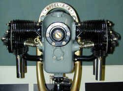 Two years later, in 1931, Continental introduced its first "flat" aircraft engine, the Model A40. This was a 40-horsepower, four-cylinder, horizontally-opposed engine with bolt-on heads and a single ignition system. One of these original A40s was on display in the classroom, and although it was pretty primitive by today’s standards, the resemblance to the later A-50 and A-65 and C-90 engines (used in Piper Cubs and Taylorcrafts) and the O-200 and O-300 (which power Cessna 150s and older 172s) is obvious.
In 1939, Continental adapted its air-cooled aircraft engines to power British and American tanks. Then, in 1945, it introduced its first "big bore" engine, the six-cylinder E-185 developed to power the original Beech Bonanza. The E-series engines evolved into the O-470 used in the Cessna 182 and, with the addition of fuel injection, the IO-470 used in the Cessna 310 and Beech Bonanza. The IO-470 was later bored (creating the IO-520), stroked (creating the IO-550), turbocharged (creating the TSIO-470, -520, and -550), and geared (creating the GTSIO-520). Along the way, the company was acquired by Henry Singleton’s Teledyne Corporation, the first American "conglomerate."
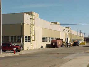
In 1970, when TCM was looking for space to expand, the City of Mobile made the company an offer it couldn’t refuse: all the space TCM could possibly ever need at the recently-closed Brookley AFB (now Mobile Downtown Airport) on a 99-year lease at the rate of $1 per year. The move from Muskegon to Mobile was made in incremental steps (the union local in Muskegon wasn’t exactly thrilled), but by 1980 the Michigan facility was history. The "new" TCM plant isn’t much to look at — mostly huge old WWII-vintage hangars that look like Quonset huts on anabolic steroids — but there’s lots of space and it’s hard to beat the rent.
…And Now
 The balance of Monday and the first part of Tuesday were devoted to an in-depth discussion of TCM’s current engine product line. We first reviewed some basics that apply to all TCM engines: model nomenclature (GTSIO-520 means geared turbo-supercharged fuel-injected opposed 520 cu. in.), data plates (blue means rebuilt, black means new, silver means a "Platinum-series" or "Raytheon Special Edition" engine), and numbering of cylinders and crankshaft cheeks and journals (all numbered from back to front, the opposite of Lycoming).
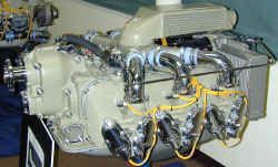
Then, we started dissecting each of the five engine series in TCM’s current product line: 240 series, 360 series, 470/520/550 "sandcast" series, 470/520/550 "permold" series, and GTSIO series. Despite external appearances that are fairly similar, each of these five engine series has quite profound differences.
 For instance, the 240 series has kidney-shaped wet sump mounted directly underneath the engine crankcase, while the other models all have integral wet-sump oil pans. The 240 and 360 series use a separate bolt-on accessory case and a front-mounted fuel pump, while in the big-bore engines (470/520/550) the accessory section is an integral part of the crankcase casting and the fuel pump is mounted to the rear of the engine. The "sandcast" and "permold" families of big-bore engines employ surprisingly different lubrication systems — the sandcast engines (front-mounted oil cooler) use an asymmetrical oil system in which oil flows forward through the main gallery in the right case half and then rearward through the main gallery in the left case half, while the permold engines (front-mounted alternator) use a hollowed-out camshaft as the main oil gallery. And so forth.
We also reviewed the two basic induction system configurations used on TCM engines. While TCM’s older designs (including the engines used on my Cessna 310, Jeb’s Debonair and Chris’s Bonanza) use an updraft induction system, the GTSIOs, 240s, 360s and some 550s use a top-mounted induction system with cross-flow cylinder heads. The latter design provides several advantages, including improved mixture distribution, volumetric efficiency, and scavenging.
 By lunchtime on Tuesday, we found that we’d learned the various TCM engine models so thoroughly that we could pretty much draw the lubrication schematics and drive train configurations from memory. We could look at an oil pump and tell whether it was from a sandcast or permold engine, or look at an oil cooler and tell whether it was a standard or non-congealing design. This was starting to get scary!
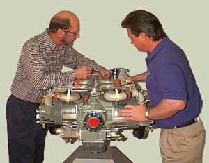
After lunch on Tuesday, we got to our first hands-on session. After reviewing the TCM video on how to remove and reinstall a cylinder, we broke up into teams, rounded up the necessary tools (cylinder base wrenches, ring compressors, pushrod tube spring compressors, etc.) and set about doing some actual cylinder R&R under the watchful eyes of instructors Billy Beam and Bob Robbins. In addition to yanking and hanging jugs, we practiced measuring cylinder fits and limits, measuring ring gaps, and the like. There was lots of kibitzing and swapping of favorite hints and kinks among the students and instructors that I found very useful. There were also a few comments about how much easier it is to change a jug on a stand-mounted engine in the classroom than in an actual airplane, where small details like baffles and cowlings get in the way.
Before we knew it, 4:30 had arrived and it was time to quit for the day.
Fuel Injection System
 Wednesday was devoted entirely to the TCM continuous-flow fuel-injection system. TCM’s Don Fitgerald, a very gifted instructor, was our guide for this segment, which I found to be one of the most interesting and useful parts of the course.
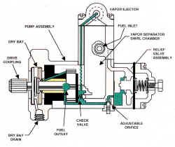
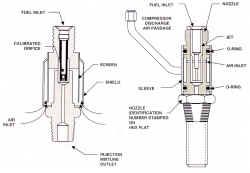
As before, the segment began with a theoretical overview of the system that applies to all fuel-injected engines. Conceptually, the TCM fuel injection system is very simple (compared, say, to the Precision/Bendix fuel injection system used on injected Lycomings). The TCM system begins with an engine-driven fuel pump whose output pressure is basically a function of engine RPM. The fuel pump output ("unmetered fuel") then goes to a fuel control unit ("FCU") consisting of two metering valves, one controlled by the cockpit-mounted mixture control and the other controlled by the throttle (along with the induction system throttle butterfly). The output of the FCU ("metered fuel") — which is therefore a function of engine RPM, throttle position, and mixture setting — then goes to a manifold valve that divides it into four or six equal parts and sends it to continuous-flow injector nozzles located in the intake port of each cylinder. The nozzles incorporate tiny air orifices that mix air with the fuel at reduced throttle settings, improving atomization.
 Conceptually simple, yes … ah, but as usual, the devil is in the details.
Turns out that there are at least five different varieties of fuel pumps used in TCM fuel-injected engines. There’s your basic pump for naturally-aspirated engines — it has two adjustments: one to set the maximum fuel pressure at takeoff RPM and another to set the minimum fuel pressure at idle RPM. A different pump is used for turbocharged engines, with the high-pressure output controlled by an aneroid referenced to upper-deck pressure. The latest vintage IO-550s use yet a third pump with three adjustments — the usual two for high and low RPM, plus a third for an altitude-compensating schedule controlled by an aneroid referenced to ambient pressure. As if this were not enough, the 240- and 360-series engines use special versions of these fuel pumps in which the mixture-metering valve is part of the pump assembly rather than the FCU.
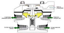 The manifold valve is also a lot trickier than it looks. In addition to its basic role as a four- or six-way flow divider, the manifold valve is responsible for providing a clean fuel cutoff when the mixture control is retarded to the idle cutoff position. It takes a bunch of moving parts — a spring-loaded poppet valve and a spring-loaded diaphragm — to accomplish this function.
The fuel nozzles come in two basic varieties, one for naturally-aspirated engines and the other for turbocharged ones. The basic difference is that the former has air bleeds vented to ambient air, while the latter has air bleeds plumbed to upper-deck pressure. The nozzles are available in a wide range of orifice sizes, and the proper size to use depends on the particular engine model and which flavor of manifold valve is installed.
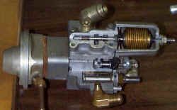
 There’s a lot more engineering wizardry in the various fuel injection system components than meets the eye. In addition to the training manual diagrams, the back of the ATATP classroom is taken up with tables covered with various TCM engine parts, including cutaways of the fuel system components. Diagrams are great, but there’s nothing like fondling the parts in your hands to ensure you understand how they are constructed and how they work.
Once we felt we understood how the fuel injection system works, it was time to move on to the practical matter of how to adjust the system. Proper fuel system adjustment is a major bugaboo of TCM engines — it’s astonishing how many engines in the field were not properly adjusted when they were installed, and have never had the adjustment checked since. It’s imperative that the adjustment be performed on the airplane, and misadjustment can cause hard starting, rough idle, premature exhaust valve failure, etc.
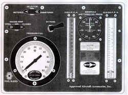 TCM Service Information Directive SID97-3 is the definitive reference for making these adjustments. The adjustment procedure requires that accurate pressure gauges be teed into the fuel system in two places — at the fuel pump output (unmetered pressure) and at the manifold valve input (metered pressure). There are four different adjustments to make — two fuel pressure adjustments on the fuel pump (high and low RPM), plus two adjustments on the FCU (idle mixture and idle RPM). These adjustments interact with one another, so it’s vital to make them in the proper order, and then to re-check them iteratively until all are within required specifications. (For IO-550-powered aircraft with the altitude-compensating fuel pump, a fifth adjustment is required, and must be made by reference to test flight results at altitude.)
After reviewing the adjustment procedure in detail on paper, the class adjourned to TCM’s fuel system test cell for some hands-on practice. This is a special room built specifically for testing and calibrating fuel injection components. Since actual avgas is used for these procedures, the room contains all sorts of OSHA-required protective devices to eliminate the risk of electrical sparks that might ignite fuel vapors, and an extinguishing system that can fill the room instantly with carbon dioxide should someone be foolish enough to ignore the no smoking signs and flick his or her Bic. (Regrettably, we didn’t get any photos of the test cell — for some reason, TCM frowned on our request to use flash photography.)
The test cell contained an actual TCM fuel system. The fuel pump is driven by a variable-speed electric motor that can simulate any desired engine RPM. Instead of typical pressure gauges, the cell uses pressure transducers connected to a PC that displays digital pressures and RPMs and logs and graphs the data. Each of us took turns adjusting the high and low fuel pump adjustments, getting a good feel for the adjustment sensitivities (PSI change per turn of the adjustment screw) and how the adjustments interact with one another.
By the time the day was done, Jeb, Chris and I couldn’t wait to slap some gauges on our airplanes and tweak the fuel injection systems into perfection.
Ignition Systems
 Thursday was ignition system day. This course segment was taught by Tim Davis, manager of technical support for TCM’s Bendix division, which manufactures magnetos, ignition harnesses, starting vibrators, ignition switches, alternators and starters. Tim previously worked for Bendix/Scintilla prior to its acquisition by TCM about 1980. Basically, he’s lived and breathed magnetos since puberty, and there’s nothing about TCM/Bendix mags that he doesn’t know.
Tim teaches with a laconic delivery that sounds precisely like Jimmy Stewart (it helps to close your eyes, since he looks nothing at all like Jimmy Stewart). Tim also has an extraordinarily dry and subtle wit that consistently had us in stitches throughout the day, making what sounded like it might be a dry subject anything but.
We started off with an hour-long short course in the basic physics needed to achieve a first-principles understanding of how a mag works. He covered the electrical properties of matter (such as insulators vs. conductors), the fundamentals of magnetism (magnetic poles, lines of flux, the inverse square law, and magnetic properties such as flux density and retentivity), and the basics of electromagnetic induction. Since this was stuff that most of us hadn’t thought about since our high school days (and promptly forgot after finals), we found it to be an excellent and interesting refresher.
 Next, Tim used these principles to explain the operation of an aircraft magneto. The mag consists of four basic components: a permanent-magnet alternator, an interrupter, a step-up coil, and a jump-gap distributor. The permanent-magnet alternator induces a modest alternating voltage (on the order of plus/minus 20 volts) in its primary coil. The interrupter (cam, points and capacitor) interrupts the current flow in the primary coil and causes its electromagnetic field to collapse suddenly. The collapse generates a high-voltage pulse (up to 35,000 volts) in the secondary step-up winding (typically a 75-to-1 turns ratio to the primary). The jump-gap distributor sends this high-voltage pulse to the appropriate spark plug lead.
While magnetos provide a highly reliable ignition source independent of the aircraft electrical system, they present some unique problems during engine start. For one thing, a mag needs to be turning at least 150 RPM to generate the 10,000 volts that is the minimum needed to produce a decent spark — unfortunately, the starter motor turns the engine at only a small fraction of this speed. Also, starting requires that the spark occur at approximately TDC, rather than the usual 20 to 24 before TDC to which mags are normally timed. Two alternative approaches are used to solve these problems. One approach is mechanical: the impulse coupling. The other is electrical: a retard breaker and starting vibrator usually referred to by the Bendix trademark "Shower of Sparks." Each scheme has its advantages and disadvantages, and we discussed them.
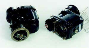
 The session next transitioned from theory to practice. Tim passed around an assortment of TCM/Bendix magnetos and watched over us as we disassembled and reassembled them. There are three basic families of TCM/Bendix mags: the compact S-20/200 series, the big S-1200 series (a favorite for turbocharged aircraft because of its outstanding high-altitude performance), and the unique D-2000/3000 dual mag (providing two independent magnetos in a single package with a single drive shaft). Each of these mag families uses significantly different construction, and by the time we were done, each of us had the chance to take each of these mags apart and put it back together again at least once. Tim also taught us how to disassemble, inspect and reassemble an impulse coupling. (Reinstalling the impulse coupling spring was easy for him, but elicited lots of colorful verbiage when we tried it.)
All TCM/Bendix magnetos require 500-hour major maintenance that includes lubricating the internal gears and bushings, and resetting the internal timing ("e-gap") and point gap. We practiced the internal timing procedure under Tim’s watchful eyes. We also practiced timing the mags to the engine, using a "buzz box" and timing gauge. And we learned how to use a harness tester to identify a faulty ignition lead.
Throughout all this, Tim provided a constant stream of hints and kinks. Never file tungsten points when they get pitted … always replace them. Pitted points often indicate that the capacitor is bad and needs replacement. High-altitude misfire can be caused by excessive e-gap, excessive spark plug gap, or contamination inside the distributor cap. Spraying ignition harness "cigarettes" with an aerosol release agent called MS-122/22 (Miller-Stephenson Chemical Co., Danbury, Conn.) before inserting them into spark plugs make them much easier to extract next time the spark plugs are removed.
I took lots of notes. Before we knew it, 4:30 had arrived and it was quitting time.
Factory Tour
 The fifth and final day of the course was largely devoted to a factory tour. I’d toured the TCM factory several times before, but those tours had been limited to an hour or so and only hit a few highlights. This tour was completely different. We literally got to see every step involved in the creation of a new TCM engine — and the number of discrete steps required to make a crankshaft or connecting rod or cylinder assembly is truly mind-boggling. Despite TCM’s huge investment in modern computer-controlled (CNC) machine tools, building these engines remains an amazingly labor-intensive process. The tour began at the beginning — in the receiving area, where crates of raw crankshaft, camshaft and connecting rod forgings and rough crankcase, cylinder barrel and cylinder head castings arrive from TCM’s forging and casting suppliers. Each of these major engine components goes through literally dozens of separate machining, grinding and polishing steps in the TCM factory to produce finished parts ready for final inspection and assembly. (In contrast, TCM purchases various other engine components, such as pistons, hydraulic tappets, pushrods, and some gears, in fully finished form.)
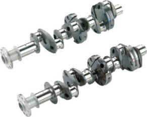
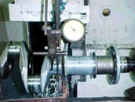 We must have spent at least an hour following the various steps required to produce a crankshaft, for example. The rough crankshaft forging must go through stage after stage of coarse grinding to create each main journal and rod journal, each operation performed by a skilled operator at a grinding machine. The operator grinds, measures, grinds and re-measures, until the particular journal is within the required dimensional specifications. When all the journals have finally been coarse-ground to the proper dimensions, the crankshaft repeats the whole sequence on a succession of fine grinding operations to obtain the final dimensional tolerances. The crankshaft is also gun bored on a horizontal boring machine to provide the required hollow center, and the counterweight hanger blades are machined and drilled. Then the crank is manually balanced on a computerized balancing machine, with metal ground off the crank cheeks as necessary to achieve the required balance. Once the machining is completed, the crank goes to the nitriding ovens where it’s baked in hot ammonia gas for some 40 hours to harden its surface. After nitriding, the crankshaft goes through several stages of cleanup and polishing. The counterweight hanger bushings are inserted, and the crankshaft goes to final inspection (where a surprisingly low number wind up being rejected and scrapped).
And that’s just for one engine part … the crankshaft!
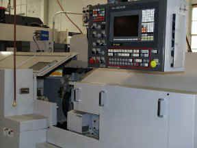 Camshaft production is a similar, but somewhat less tedious and more automated process. At the time of our tour, roughly half of TCM’s camshaft production was being done on a brand new state-of-the-art CNC machine that TCM acquired just this year, while the other half was still being done on a pair of vintage mechanical cam grinding machines. Once cam production is completely converted over to CNC, we were told, TCM will be making some engineering improvements to their cam lobe contours that could not be accomplished using the old equipment. After grinding and polishing, the camshafts are case-hardened (carburized) in an oven, then cleaned, polished, and coated with manganese phosphate for corrosion protection.
Production of connecting rods — among the most highly stressed components of the engine — was particularly interesting. Each con rod starts out as a single rough forging. The crankshaft end of the rod is sawed in two to separate the rod cap. Then semicircular sections are "hogged out" of both the rod cap and the big end of the rod on a giant vertical mill to rough out the big-end bore. The rod and cap are then reassembled, the rod bolt holes drilled, the rod and cap mated up, and then the bores are precision milled, chamfered and polished. Again, it was surprising to learn how many individual machining steps are required to produce a finished connecting rod.
 The story was much the same for cylinders and crankcases, except that TCM has pretty much fully converted to modern CNC equipment for machining case halves, cylinder barrels and cylinder heads. One of the most mesmerizing sights, however, was to watch the heads and barrels being mated together in decidedly low-tech fashion. A factory worker wearing protective gloves removes a hot cylinder head assembly from the oven and quickly places it in a fixture. The worker then inserts chilled intake and exhaust valve seats into the head before it begins to cool. (As the head cools, it creates a permanent interference fit with the barrel and valve seats.) Then, he positions the cold barrel against the hot head and spins it to mate the threads. We just couldn’t get enough of watching this particular factory worker’s rhythm as he processed about one new cylinder assembly per minute. (Later, we were sad to learn that TCM was about to reassign the job of inserting the valve seats to a new CNC machine. The result will undoubtedly be more consistent positioning of the seats, but it’ll sure take away the romance.)
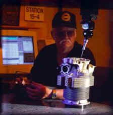
 After many fascinating hours spent watching how these various engine components are produced, we proceeded to final assembly where the engines are actually built up. A job in final assembly is perhaps the most prized position to which a TCM factory worker can aspire, in large measure because the final assembly area (which occupies only about 2,000 square feet of TCM’s enormous plant) is one of the very few places in the factory that has air conditioning.
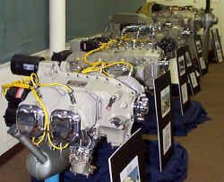
Half of the final assembly area is devoted to a classic production line, in which engines move from station to station and as buildup progresses. There is only a single assembly line that accommodates all engine models, new and rebuilt alike. (I found this to be a marked contrast to Lycoming, where new and rebuilt engines are built on two separate lines.) The other half of the final assembly room consists of small assembly bays accommodating one engine each. If assembly of a particular engine is delayed due to parts availability, for example, it will be pulled off the assembly line and moved to one of the bays so as not to hold up the rest of the engines on the line. The same is true of any engine that requires special attention for whatever reason — such as the special one-of-a-kind ultra-high-horsepower TSIO-550 engine that TCM built up for use at the Reno National Air races.
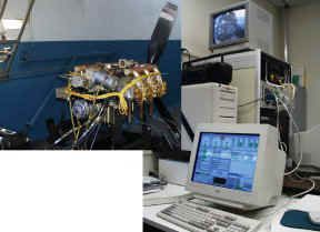 Our tour ended at TCM’s production engine test facility, where every engine that comes off the TCM line is run through a programmed series of test procedures. The facility contains six computerized engine bays, and the test sequences are controlled and monitored by computers and supervised by test technicians who use mouse clicks rather than knob twists to regulate what’s going on in the test cells. Each cell is monitored both by computer instrumentation and by closed-circuit TV. The TV pictures and computer readouts are also piped to a central control room where the production test supervisor can keep track of the goings on in all six cells concurrently.
This was a genuinely fascinating day for all of us, and we came away with a far better appreciation of just how much effort goes into the production of a piston aircraft engine … and why they cost as much as they do.
Time To Go
 Late Friday afternoon, as we said our goodbyes to our instructors and fellow classmates and packed up our precious course materials to be shipped home, Jeb, Chris and I compared notes. We all agreed that the course had been extraordinarily worthwhile, and that we’d learned far more than we’d expected. Beyond the formal curriculum, we remarked on how valuable it was to have the chance to get to know so many subject matter experts at the factory on a first-name basis. The week had been educational, stimulating, fascinating and fun, and we were all sorry to see it come to an end. Without question, we all felt it was time and money well spent.
If you’d like to become a real expert about your TCM powerplant and can find the time to spend a week in Mobile, I can’t recommend this course highly enough. If you can drag your favorite mechanic along, so much the better. I promise you won’t be sorry.
The ATATP classes are typically booked up months in advance, and pre-registration is a must. Contact Billy Beam at 1-334-436-8660 or by email at [email protected].
