


During training and checkrides, pilots are expected to be able to use all the features of a glass panel including the autopilot. In this article we’ll address some of the intricacies of addressing that challenge. This is especially relevant to instrument rated pilots who have mainly flown round gauge airplanes without autopilots and flight directors.
The information contained herein is subject to possible exceptions. If you’re new to autopilots, get proper instruction from knowledgeable sources and thoroughly study the manual.
Another trend in recent years has been the introduction of sophisticated retrofits. For example, the Garmin GFC 500, which is being installed in many fixed gear, round-gauge airplanes.
Training With Autopilots
It’s common practice in jets and even light general aviation airplanes (with sophisticated autopilots) to engage them shortly after take-off and leave them on until short final. For example, a G1000 C182 POH allows the unit to be engaged at 800 feet AGL for all flight phases, but must be disconnected at 200 feet AGL during an approach. The autopilot also has limitations of maximum and minimum indicated airspeeds.
This philosophy of engaging the autopilot for most of the flight may result in an overreliance on its use. As is usual in aviation, often there is no right or wrong answer. With it on, the pilot can oversee the flight and delegate the “routine” part of aircraft control to George.
Paradoxically, pilots tend to be more heads down with the autopilot engaged in VMC compared to hand flying, which requires more heads-up. In IMC, clearly they are a big help; however, any instrument rated pilot that only flies in IMC with the autopilot engaged may be setting the stage for trouble.
Terminology
Most autopilots in light general aviation airplanes are two-axis, meaning they control roll (longitudinal axis) and pitch (lateral axis). I’ve heard pilots say they have a three-axis because it has altitude hold mode.
This implies that altitude hold controls a “third axis.” There is no third axis in airplanes associated with altitude. Some planes do have a three-axis autopilot, the third axis (vertical axis) commonly referred to as a “yaw damper,” controls or minimizes unwanted yaw to address fish-tailing in turbulence like many aircraft do. This article will focus on two-axis units.
Types Of Autopilots
There are two main types of autopilots: 1) Attitude-based that rely on the attitude indictor or attitude and heading reference system (AHRS as found in glass panels) for pitch and bank information, and 2) Rate-based autopilots that use a turn coordinator for pitch and roll information. In general, attitude-based tend to be more precise compared to rate-based, but there are many excellent rate-based systems.
Examples of rate-based include the Bendix/King KAP 140 and nearly all S-TEC systems. In some installations, the turn coordinator is installed behind the panel and not visible to the pilot. Attitude-based units include the Bendix/King KFC 150 and many Century and Cessna/Sperry systems. Additionally, the autopilot might have a flight director.
Flight Modes
There are typically two flight modes: lateral and vertical. Note that these terms (as used here) do not refer to the aircraft axis. In the lateral mode, the autopilot will fly a heading set by the heading bug on the directional gyro or horizontal situation indicator (HSI) or follow a GPS course with GPSS capability (discussed later). NAV mode is another lateral mode where the autopilot follows the movement of the CDI needle. Lateral mode could also allow it to function as a “wing leveler”—sometimes called ROL mode.
In the vertical mode, the autopilot could hold altitude or could make the airplane climb or descend to a predetermined altitude at a selected climb or descent rate and then hold the selected altitude.
Autopilots also have approach mode (APR) that combines both lateral and vertical modes and is usually engaged during coupled approaches—allowing the airplane to fly an ILS or GPS glideslope. autopilots might have other lateral and vertical modes, so be sure to fully understand the specific manual.
GPSS—Steering
GPSS is a useful lateral mode. Typically, a NAV source (GPS or VOR) would drive the course deviation indicator (CDI) on an HSI or traditional round gauge VOR/LOC/GPS head. The CDI, in turn, would provide lateral input to the autopilot.
In some retrofit installations we may have a digital NAV source (specifically GPS) driving an older analog unit. The autopilot would be wired through a “digital converter” that interfaces the GPS source with the autopilot, meaning that the CDI is completely bypassed. In effect we are tricking it into thinking it’s in Heading mode GPSS mode is chosen by a toggle switch; however, the autopilot is in heading mode. Sounds counter intuitive. The autopilot follows GPS instructions as if they were heading commands, something the engineers call “heading emulation.” This allows the airplane to fly curved courses (but not radius-to-a-fix) such as holding patterns and anticipating turns in fly-by waypoints.
The other toggle mode is HDG, which allows the autopilot to fly the heading selected in the HDG bug. NAV mode on the autopilot is used when flying a VOR course and in APR mode during ILS and GPS approaches. In this case, the autopilot is following the commands from the vertical and lateral CDIs.
Failure Modes
Inputting a task into the autopilot and discovering that the airplane is doing something different than expected elicits the natural comment: “why is it doing this.” Most perceived failures are not “failures,” but pilot input error. Once we determine that the ensuing failure is pilot induced, we can correct it.
Aside from pilot-induced errors, typical failure modes are covered in the manual. They fall into two broad categories. True autopilot failure—a control servo fails, or the control (computer) decides to go on strike or perhaps a switch fails. The other more common failure is that of an input source. For example, if the AHRS or a NAV input fails, the autopilot also will fail in some fashion. In the former instance, it will simply not operate. In the latter case, it may continue to operate but will not fly a chosen course. In attitude-based autopilots using a vacuum driven attitude indicator, the failure of the vacuum pump will result in an inop autopilot.
What is critical to know is not only that a failure has occurred but its root cause. The pilot needs to be able to quickly identify that a failure has occurred, handle the failure itself, and then identify and address the root cause. However, there is one obvious first response: turn it off and hand-fly since aircraft control is always the pilot’s first priority. Then troubleshoot when time permits.
Turning Off The Autopilot
It is important to know the various ways to disengage the system:
- press the red button on pilot’s yoke,
- toggle ON/OFF switch,
- pull relevant circuit breakers,
- turn OFF the pitch trim,
- manually use elevator trim,
- turn the airplane master OFF
Of course, by turning off the master switch, all electrical power will be lost (except for the magnetos of course). Know the various ways to turn off the autopilot in your airplane.
In 1972, there was a well-known Lockheed L-1011 CFIT crash in the Florida Everglades caused by an inadvertent disconnect apparently caused by inadvertently moving the controls while the flight crew was troubleshooting what appeared to be a landing gear extension problem. The L-1011 tragically flew into the swamp. This accident highlights that whenever the autopilot is engaged, the pilot must constantly monitor its operation.
There might be a situation when even turning off the master switch is not enough. This would be a rare case because the autopilot needs electrical power to operate. The fault might be the result of mechanical binding of the flight cables or control rods or perhaps a servo clutch that freezes. This may require brute force to control the airplane and could be an emergency if the result is a pitch down force.
A Simple “Trick”
If pilots mentally (or through mumbling) verbalize what they want the autopilot to do, this will usually result in inputting the correct commands. “I want to turn right to a heading of XXX degrees and climb at YYY FPM to a ZZZ altitude.” At least five or six inputs are required. Try it and let me know if it helps. As a final note, the FAA interprets FAR 61.51 to allow pilots to log PIC time while the autopilot is on. This implies that flying a coupled approach meets the requirement for instrument currency.
The Need For Adequate Autopilot Training
The Instrument ACS Preflight Procedures, Task B, requires that pilots “demonstrate an understanding of…the Flight Management System (FMS) and autopilot.” Additionally, Task C requires knowing “limitations of flying with inoperative equipment,” which includes the autopilot. During an IPC, a pilot may be asked to demonstrate autopilot use and failure modes. Many new production aircraft typically have glass panels (e.g. Garmin G1000) with integrated flight instruments, avionics, and autopilots. The availability of more retrofit systems also means more round-gauge airplanes will be so equipped. Due to last year’s changes in FARs and FAA policy, a Technically Advanced Aircraft (TAA) may be used in place of a complex airplane for the commercial certificate and for CFI-SE and commercial practical exams—resulting in more APs in flight schools, flying clubs and the rental fleet. This points to the need for adequate training in their use. In the past, some
CFIs specialized in instructing in specific avionics, this should include autopilots. The instructor need not be a CFI; avionics pros could be used (although, this instruction time would not count for training towards a rating or operating privilege). Another implication is that rental check-outs might be more extensive— requiring a review of the autopilot to include:
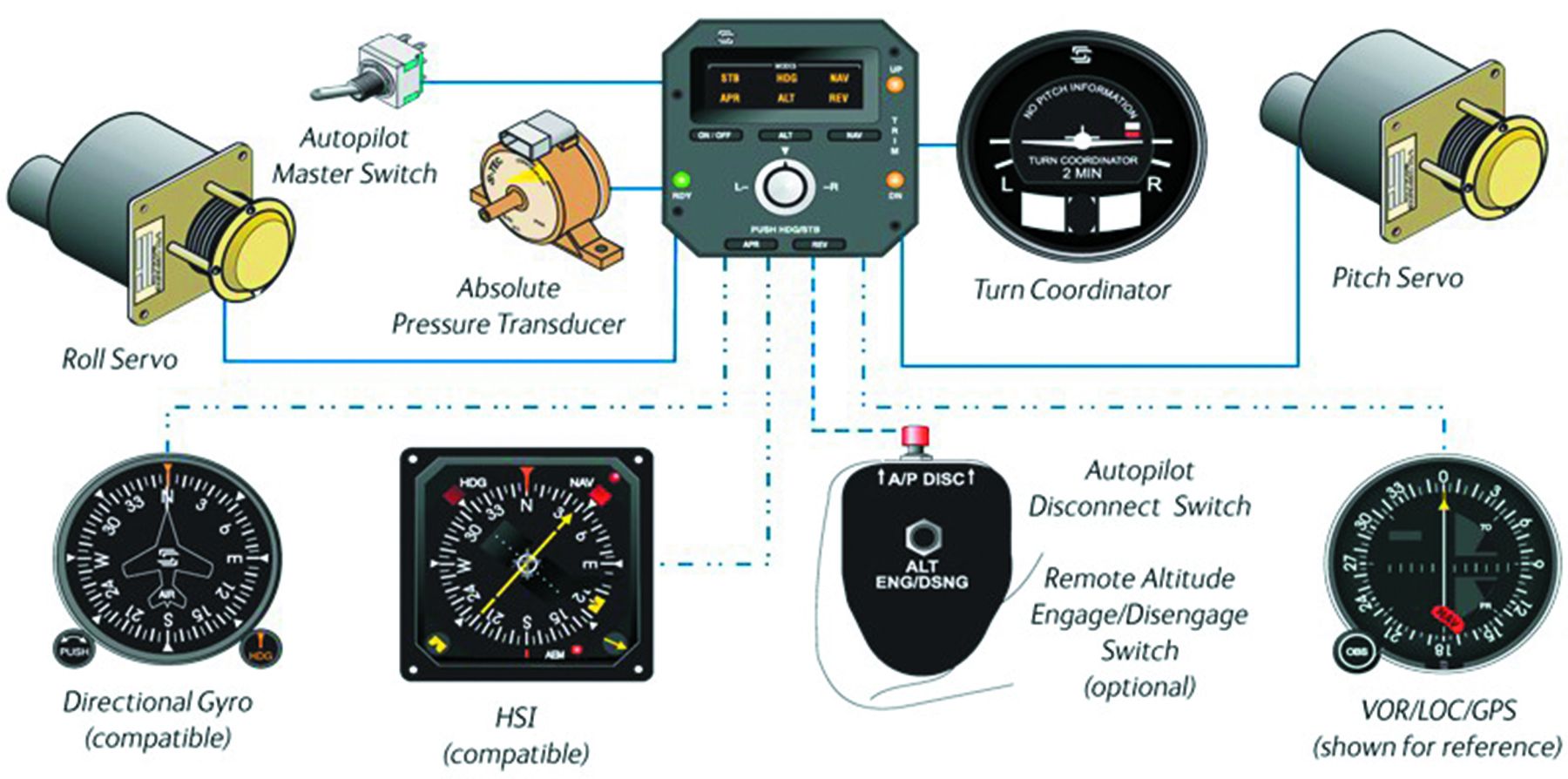
- Overall system design using a schematic like the one above. AP components and information feeds—for example, nav sources, and altitude (baro) information.
- Understanding the various modes, how to engage them, and the expected outcome.
- Knowledge of all possible ways to disengage the AP.
- Failure modes and those associated with information input. For example, failure of the single vacuum pump in an airplane with an attitude-based AP using a vacuum attitude indicator results in an inoperative system.
- Where to look to confirm the active mode; could be on the AP, a PFD, a remote indicator, or a combination.
- How the AP integrates with the FMS and/or flight director, if present.
- During the run-up, how to check AP performance. Some self-check themselves once the avionics master is ON, some require pilot input, or both.
- Limitations of use, for example airspeed, altitude, use of flaps, etc. Also, any constraints in their use during instrument approaches and missed approaches.
Finally, note that integrated glass cockpits are type certified by the airplane manufacturer—not by the manufacturer of the avionics. This means that a G1000 in one airplane make/ model, may have different features compared to another make/model. While this might sound trivial, the pitch trim indicator of a G1000 Mooney is in the G1000, not so in a C182. In general, annunciators and alert levels will be different.
Luca Bencini-Tibo ATP/CFII, is a FAASTeam Lead Rep, aircraft owner and a graduate of MIT.
This article originally appeared in the May 2019 issue of IFR Refresher magazine.
For more great content like this, subscribe to IFR Refresher!
