


As instrument pilots we are aware of many things that are important to safe flying. Of the many critical items, one that often gets neglected is runway markings—literally the “paint” on the runway, as opposed to runway and taxi lights and signs. Needless to say, I’m referring to paved runways, not grass strips nor waterways for seaplanes. Perhaps we take runway markings for granted simply because we expect them. We do expect runway designators i.e. “runway numbers” and centerline markings. Let’s explore in more detail runway markings and their relationship to instrument operations.
Take-off Minimums
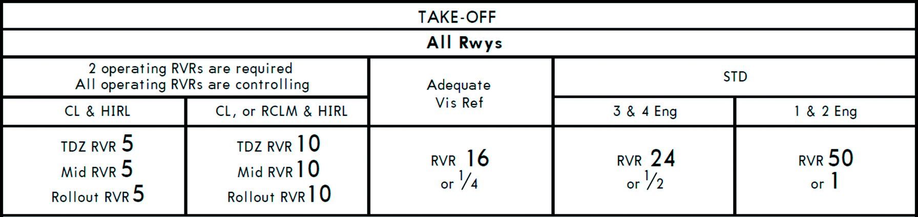
As Part 91 pilots, under IFR we are legally able to take off in zero-zero conditions, though that’s probably not a wise nor safe decision. This is not the case for airline operations (Part 121). Using Orlando International Airport (KMCO) as an example, standard take-off minima require a visibility of one mile (or RVR 50) for one and two engine airplanes and a visibility of one-half mile (or RVR 24) for three and four engine aircraft. (See KMCO Take-Off minima table below).
However, the minimum can be reduced to a visibility of one-quarter mile (or RVR 16) with “Adequate Vis Ref.” While the FAA does not define what “adequate visual reference” means, it probably refers to the ability of the pilot to maintain the runway centerline during the take-off. Furthermore, in airline operations with OpSpecs approval, takeoff minima can be further reduced to RVR 10 with Runway Centerline Markings (RCLM) and High Intensity Runway Lights (HIRL) or Centerline Lights (CL). With both CLs and HIRLs, the visibility required drops to RVR 5 without requiring RCLMs.
While it would be legal to take-off with an RVR of 500 feet, landing back at Orlando wouldn’t be allowed due to a higher landing visibility minimum for ILS CAT I. Such an operation under FAR 121.617 would require a “take-off” alternate within one hour flying time for two engine airplanes with one engine inoperative. The rule allows two hours flying time for airplanes with three or more engines.
For Part 91 operations in a twin, perhaps consider a take-off alternate with acceptable weather no more than 100 to 140 miles between the departure airport and alternate airport when faced with a takeoff visibility less than landing visibility.
Landing Minimums
Another way that runway markings could affect us are straight-in landings. The FAA Instrument Procedures Handbook (H-8038-16B) states that a “circling only” approach is required if:
- Final approach course alignment with the runway centerline exceeds 30 degrees or,
- Rate of decent exceeds 400 ft/NM from FAF to the runway threshold or,
- A runway is not clearly defined on the airfield.
It’s this third condition that is interpreted (in part) by the FAA to imply the “runway is not clearly defined” if it lacks instrument runway markings. In a previous article in IFR Refresher (Sept. 2016) we discussed that the RNAV approaches to RWY 10 and 28 at Lantana Airport (KLNA) are marked circle-to-land even though they are straight in approaches. Besides the runway numbers, it only has centerline markings.
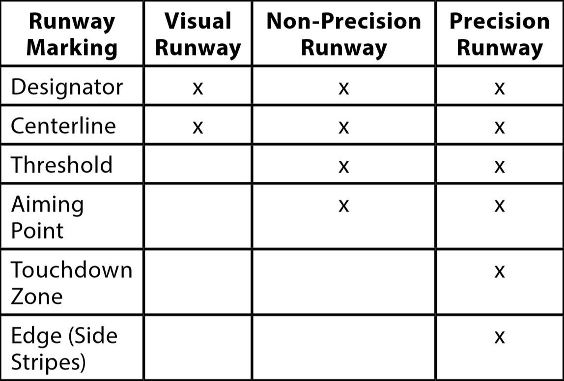
Precision Runway Markings
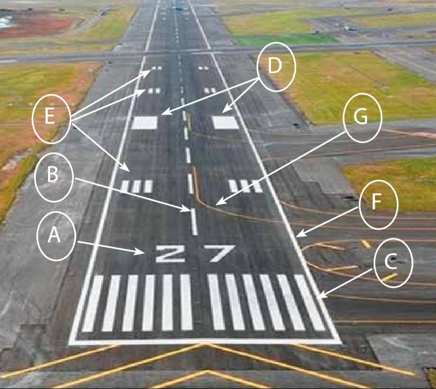
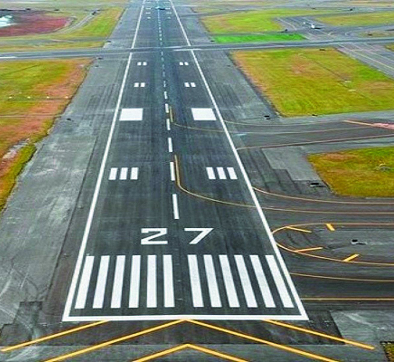
The following definitions are keyed to the photo on the right of an approach to runway 27.
Runway Designator (A): This is the magnetic azimuth of the centerline of the runway to the nearest 10 degrees. As variation changes, periodically the runway numbers change. In Florida, we’ve had a number of runways renumbered, implying “new paint” and changes to approach and en route charts and procedures.
Runway Centerline Marking (B): Provides alignment guidance during take-off and landings. Those were the markings that our primary instructors stressed that we were supposed to straddle with the landing gear—not to one side or the other. In CAT II and CAT III and some CAT I approaches, lights are also imbedded along the runway centerline to provide improved visual reference.
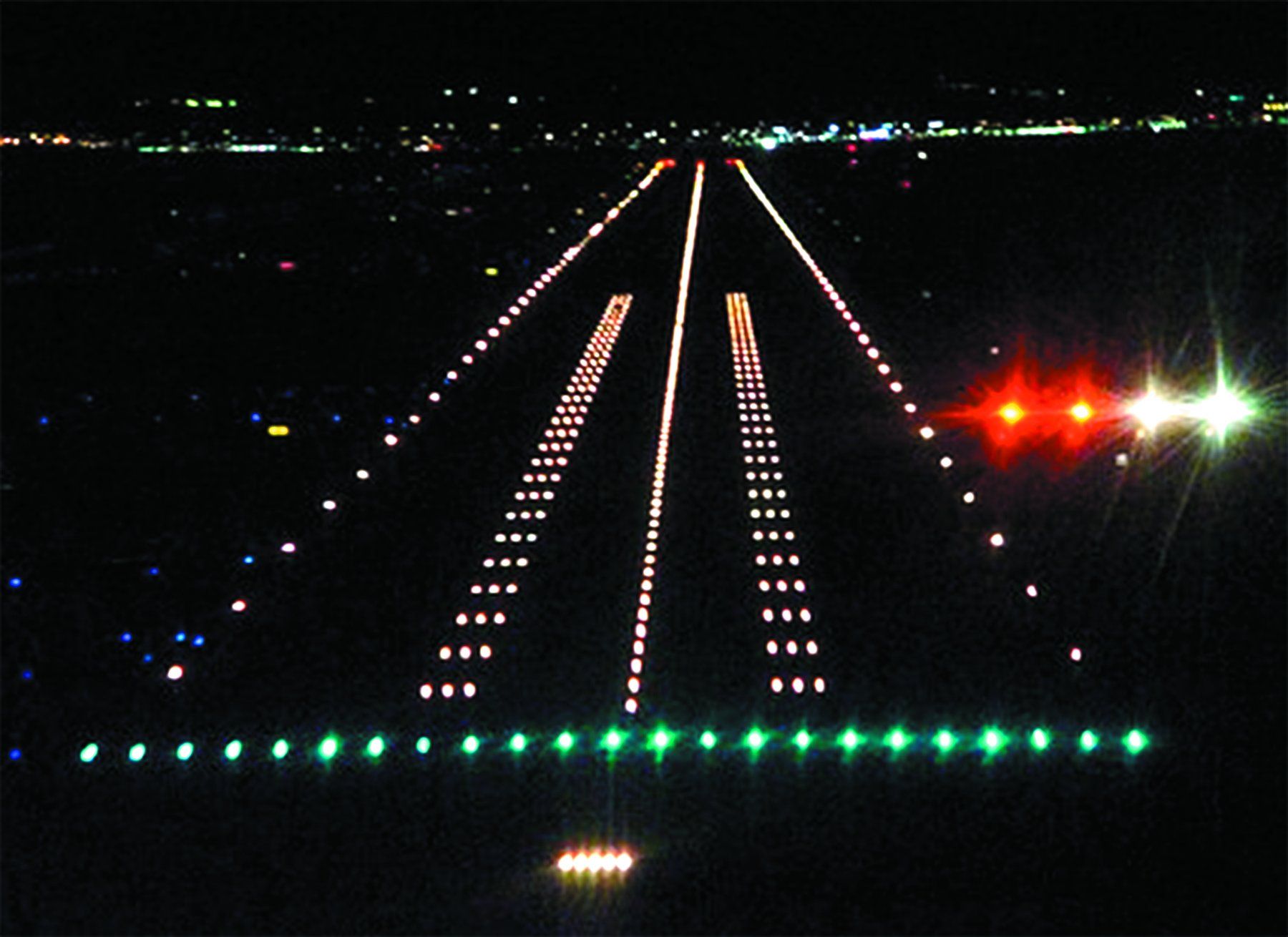
Runway Threshold (C): Helps to identify the beginning of the runway that is available for landing. At night, the threshold is identified by green lights as seen from the approach side.
Runway Aiming Point (D): The “big white rectangles” used as the aiming point for landing. Technically, that’s where a glideslope (ILS or LPV) would run into the ground.
Runway Touchdown Zone (E): Identifies the touchdown zone for landing. Sometimes lights are also imbedded in this zone.
Runway Edge Markings (F): Identifies the edge of the runway and the “start of grass.”
Taxi-line Markings (G): Some runways also have yellow taxi lines for guidance to exit the runway.
Interesting Points
If a runway has a precision approach in one direction, but not on its reciprocal direction, the whole runway will have precision markings.
RNAV approaches flown to LPV minima are technically considered non-precision approaches. Per ICAO definition, they are APV: approaches with vertical guidance. However, the FAA (for purposes of instrument rating practical tests and instrument proficiency checks) allow LPV approaches to be considered precision approaches if the DA is 300 feet or lower.
The length of a centerline stripe is 120 feet and the distance between the stripes is 80 feet, resulting in 200 feet between the start of a stripe and the start of the following stripe.
Likewise, the length of the aiming point markings is 150 feet. These are often used to practice precision landings where the wheels touch at a pre-determined point on a runway (200 feet for private standards and 100 feet for commercial standards). Either reference can be used for this purpose.
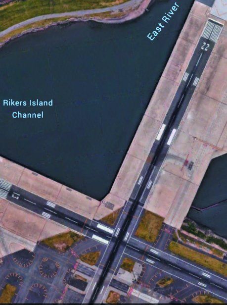
When runways cross, the markings have an order of precedence depending on the type of approaches. The order of precedence is: CAT III, CAT II, CAT I, non-precision and visual.
Note in the photo on the right that the RWY 22 markings at La Guardia have precedence over RWY 13 markings. RWY 22 has an ILS CAT II while RWYs 13 and 31 have ILS CAT I.
Displaced Threshold
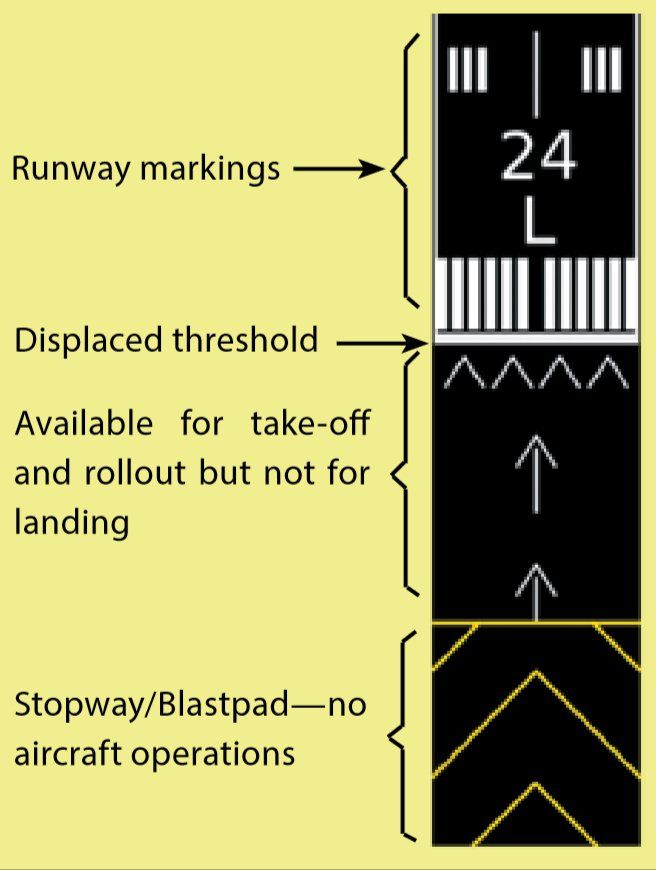
Usually displaced thresholds are used when there are obstacles along the final approach course or for noise mitigation. It keeps landing aircraft at a higher altitude during the approach. Displaced thresholds can be used for take-off and roll-out from the opposite runway but not for landings.
Needless to say, displaced thresholds impact available landing runway length. However, sometimes displaced thresholds are part of a taxiway leading up to the runway and would have taxiway markings instead of displaced thresholds. Rarely there are combinations of taxiway and displaced thresholds. The taxiway part cannot be used for take-off.
Stopways And Blastpads
These are not designed to be used for routine airplane operations, specifically landing, take-off or taxiing.
Some stopways have Engineered Material Arresting Systems (EMAS), which are usually charted on airport diagrams. EMAS are “high energy absorbing materials of selected strength, which will reliably and predictably crush under the weight of an aircraft.” EMAS is meant to stop an aircraft within the runway environment with no human injury and minimal aircraft damage. At LaGuardia airport (KLGA) in New York, there is water at the end of all runways, thus it has several EMAS areas as depicted on the airport diagram.
Currently there are over 100 EMAS installations at 63 airports, and more to come. Clearly, we would not want to inadvertently taxi on a stopway with EMAS, as it could be difficult and expensive to extricate the plane.
Runway markings provide important information and their presence demands your recognition of their significance.
Reference: AC 150/5340-1L
Luca Bencini-Tibo ATP/CFII, is a FAASTeam Lead Rep, aircraft owner and is a graduate of MIT.
This article originally appeared in the October 2018 issue of IFR Refresher magazine.
For more great content like this, subscribe to IFR Refresher!
