


")

")


This column is a continuation of previous columns about manifold pressure(MP), props, mixtures, and engine management techniques. They are listed here for your reference. Reviewing them might be a good thing to do before venturing further into this one!
This column is something of a historical perspective on the general subject of superchargers. It is sometimes helpful to review where we’ve been, so we can better understand how we got here. I hope to make the next column highly specific to the modern “turbonormalizer” as installed by Tornado Alley Turbo. Operating procedures will follow, either in the next column or the following one.
What Have We Learned So Far?
We have learned that manifold “pressure” in a normally aspirated engine with a wide open throttle is nothing more than ambient pressure, reduced slightly by the drag of a filter, and by additional drag from a pipe with bends in it. By closing the throttle, we constrict (or “throttle”) that airflow even further, creating suction (lower pressure for the purists) in the pipes downstream of the throttle plate. This suction is created by the action of the pistons literally pumping air, sucking it into the engine.
When you think “I’d like to throttle that FAA inspector,” you are contemplating doing the same thing your engine’s throttle does when you close it. You literally strangle your engine by cutting off its air. At idle, you have cut off so much air the engine can barely run. The only purpose of a throttle is to restrict air going into the engine.
It is also worth noting that a partially closed throttle is exactly the same as running with a dirty filter.
We have learned that the RPM of a constant speed prop is governed by flyweights, springs, oil pressure, and aerodynamic forces, all working together (or against each other) to produce an RPM selected by the pilot – provided there is enough engine power and/or enough wind (airspeed) to turn it at the desired RPM.
We have learned that the mixture control changes the RATIO of fuel and air, and that the “old wives’ tale” (OWT) that “leaner is hotter” is true only to a point (peak EGT or peak CHT), after which “leaner is cooler.” Not to mention cleaner.
We have learned that the mixture has more control over power output than anything else, for it can vary the power from full rated power to none at all. It is very important to understand that a given MP and RPM setting does not necessarily produce the power the book states, unless you also adjust the mixture to the fuel flow that goes along with that power setting.
We have learned that for any given power setting, a mixture on the lean side of peak EGT will produce cooler CHTs than a mixture setting rich of peak EGT. The engine running lean of peak EGT will need a bit more MP, or more RPM, or both, to produce that same power.
We have learned that the interplay of these three controls has a number of important effects on what happens in the combustion chamber, changing the temperatures, pressures, burn rates, and the very character of how the temperatures and pressures build and fade during each combustion event.
If you do not clearly understand each of the items in this mini-review, then please do yourself a favor, and go back and read one or more of those previous columns.
Pumping It Up
Fairly early in this flying game, it became obvious that increased altitude meant a power loss in the reciprocating engine, since the lower pressure up there at altitude meant “thinner air” and fewer molecules of oxygen to mix with the fuel. At about 18,000 feet, there is only half the pressure, and therefore about half the molecules of oxygen for any given volume of air. The pistons still pump up and down the same distance (stroke), with the same diameter (bore), and thereby pull in the same volume of air as at sea level, but there is less mass to it, so there’s less to burn. Not surprisingly, a normally aspirated engine will only produce about 50% of its maximum power at 18,000.
Some method was needed to pump more air, and produce a greater pressure in the intake system.
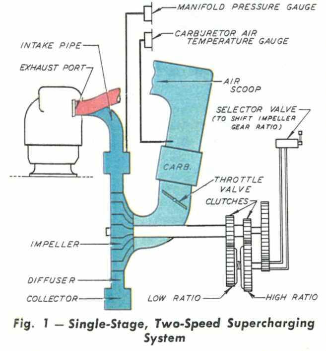
Since these engines use vast quantities of air, it is impractical to carry heavy tanks of compressed air, so the only way to get past this problem is some means of taking in and compressing the available air, regaining some of the lost power. One early method simply drove a compressor off the accessory section of the engine. Early engines like this had a simple system, just a single impeller, with fixed gearing, as on the Twin Beech, or the AT-6. Rather quickly, designers found out that even higher altitudes could be attained with a two-speed arrangement, with a shifter mechanism to change the gear ratio in flight.
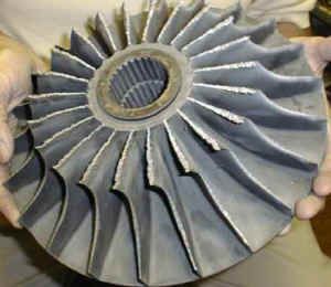
When we mount a “compressor” on an airplane engine, we give it a fancier name, calling it a “supercharger” (nicknamed”blower”). The heart of this device is called an “impeller,”and is usually a wheel with many blades on it, turning at a speed much higher than the engine itself. Early superchargers were geared directly to the back of the engine in the accessory section usually turning roughly ten times the speed of the crankshaft. The impeller pictured here came from a Pratt & Whitney R-2800 mounted on a Grumman F8F-2 Bearcat, and shows major damage caused by someone failing to tighten some nuts in the air passages.

Naturally, some of the useful engine power is lost by driving this device,but on balance, the increased power more than makes up for it. Further sophistication was added to some, with multiple stages (more impellers), or multi-speed superchargers.
Engine Identification Nomenclature |
This type of “gear-driven” supercharger is common on the bigradials, and on some “flat” engines as well. This is usually denotedby an “S” in the engine model, as in GSO-480, which would indicate a (G)eared (S)upercharged engine in a horizontally-(O)pposed engine. These were found in airplanes like the twin Aero Commanders, Queen Airs, and Twin Bonanzas, to name a few.
In general, these gear-driven supercharger systems will produce much higher manifold pressures (and greater power) than the equivalent normally-aspirated engine. Some will produce up to 60 inches instead of the usual 29 inches at sea level in a normally-aspirated engine, and some of the Reno racers jack the MP up to as much as 120 inches! Most of these installations will produce far more than maximum power at full throttle, so it is usually necessary for the pilot to stop the throttle at some point well before reaching the mechanical stop, to avoid over-boosting the engine. If you’re in the habit of simply pushing the throttle forward to the stop, you’re in for a rude surprise with one of these.
There are several ways for the fuel to be inserted into the air in these engines. In some, the fuel comes in at the carburetor. In others, it is injected at the blower, so the impeller causes better fuel/air mixing and fuel atomization. Some, like our common “flat sixes,” inject the fuel at the intake valve, and in at least one variant of the supreme Wright R-3350 the fuel was injected directly into the cylinder in carefully measured squirts, at just the right time. The complexities of this “direct fuel injection” would fill a book themselves, and are well beyond the scope of this work.
Enter the Turbo
Now let’s look at the exhaust side of the engine. Just as the engine takes in huge quantities of air, so it must expel it. Not only does it expel all the air it takes in, but also the additional hot gas produced by the burning of fuel. It wasn’t too long before some bright person had the neat idea of extracting some energy from that massive flow of hot gas, and the easiest way of doing that is to stick a wheel made of high-temperature metal with blades on it into that stream, just as you might stick a water wheel into a river, or as a child holds a pinwheel in the wind. Any device that is spun by gas or a fluid is called a turbine, and it converts the energy of a moving mass of gas (or liquid) into a mechanical spinning motion. Lots of motion! Some of the little turbines in our GA airplanes turn up around 100,000 RPM or more. These little wheels get hot, too, with upper limits of 1,650°F when made of older stainless steel alloys,and up to 1,750°F when made of Inconel. Above these temperatures the metal begins to soften, and if high RPM is also present, the metal will “creep” with potentially catastrophic results. Even though these tiny turbines are only a few inches in diameter, at that RPM they are potential bombs. Fortunately, the designers have learned their lessons well, and such catastrophic failures are now exceedingly rare. It is worth emphasizing here that limit temperatures are by themselves not dangerous. It is only when both limiting temperatures and limiting RPM are present together that we begin to venture onto dangerous ground. One day, someone will develop a turbine made of some sort of ceramic, and we may be able to extract even more energy from the exhaust stream, and put it to work.
Okay, now we’ve got that little hummer rotating madly in the exhaust stream, what do we do with it? Several different methods have been implemented to make that rotating force useful. One method used on the big radials like the Wright R-3350 was to have the turbine shaft hooked to a fluid drive (like a car’s automatic transmission), and the output of that drive was geared directly to the main engine crankshaft. This was called a “Power Recovery Turbine” (or PRT) and was common on DC-7 and Lockheed Constellation aircraft, recovering about 500 net horsepower per engine.
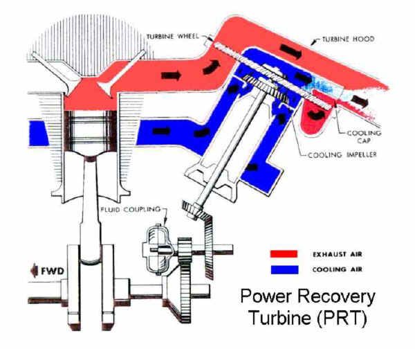
But nothing is free in physics, and the cost here is weight and considerable complexity, plus an increase in backpressure, which always steals power. Pilots are quick to give pet names to many things, and one name for the PRT was “Parts Recovery Turbine.” The turbine wheel was very tightly shrouded, and with any uneven heating, or slight misalignment, it might rub, that spot might overheat, spark, and eventually cause the dreaded “PRT fire.” There were not nearly as many as you might believe from hearing the old pilots talk, but the few that did occur were serious enough to run the pucker factor off-scale. Especially over the North Atlantic, at night, with ice and weather!
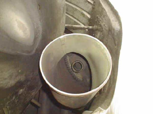
PRT Wheel Inside Exhaust Stack
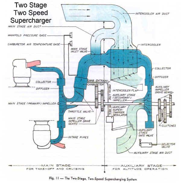
Some engines, like the Wrights on the B-17, had the best/worst of both worlds, having both a turbo for initial boost, with the output from the turbo feeding the usual geared supercharger.
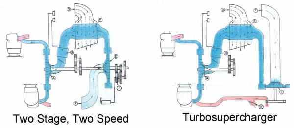
In the picture on the left, there are two separate impellers, both driven by gearing in the accessory section of the engine. On the right, hot exhaust runs a turbo, which serves as the first stage. Both have their advantages and disadvantages.
This is another variation by Wright, and is very similar to the installation on the Boeing B-17 “Flying Fortress.” This was the reason the airplane was such a success on high-altitude bombing missions. There are a few B-17s left flying today, and most, if not all, have the turbo portion of the system disabled, because it is complex, hard to maintain, and no one needs to carry a full load of bombs to 25,000 feet, anymore. At least one wit calls these “castrated B-17s.”
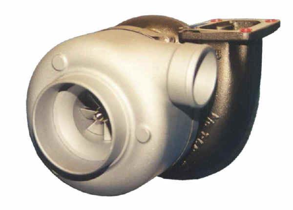
The turbo method alone seems to be most common today in GA airplanes, with both the turbine and the impeller on the same shaft. By placing the turbine wheel in the stream of hot gas, we drive the impeller, which sucks in ambient air and compresses it before sending it on to the engine. That little shaft that connects the turbine to the impeller is a critical part, for it is spinning at the full RPM, too. It must be lubricated very well, in order to keep it from ever making metal-to-metal contact. The metal parts nearby get quite hot, so it is necessary to pump a fair amount of oil through the shaft bearings, both to cool them, and to keep the oil itself from getting cooked in the process.
It is important to remember that no air transfer takes place between the turbine side of the turbo compressor, and the impeller side. The turbine side sees only the hot exhaust gas from the combustion process, which is measured and displayed “Turbine Inlet Temperature” (TIT). Once the exhaust has turned the turbine wheel, there is no further use for it, so it is dumped overboard. That must be one confused bunch of molecules! They have been sucked up, squeezed, sliced, diced and atomized, squirted with a foul liquid, burned to a crisp, rudely shoved into yet another slicer and dicer, and then casually tossed aside like an old girlfriend, probably wondering “What happened?” All in the space of a few milliseconds.
On the other hand, the impeller side sees only cool outside air and simply compresses it. In fact, that air remains so “clean,” it can be breathed safely, and so it is sometimes used to pressurize cabins.
Those pesky laws of physics interfere here, because when a gas is compressed, it is heated, and the hotter the air is when it enters the combustion chamber, the less useful power we can extract from it. Logically, if you double the pressure, you should double the power, but some of that is lost with the heating that comes with the process. Ambient air that enters the compressor portion of the turbo is, of course, at roughly ambient temperature. The air leaving the compressor is measured and sometimes displayed as CDT, or “Compressor Discharge Temperature,” and it can get hot indeed, over 260°F at high altitude, and high power.
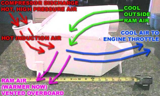
For this reason, many supercharging systems, both old-style and new, will have an “intercooler.” This is nothing more than a heat transfer device, generally with no moving parts. The heated air coming from the supercharger is simply run through a radiator, which is cooled by ambient air. The cooling air is usually ram air, so the only penalty here is the small amount of aerodynamic drag from the extra air scoops, and the slight additional drag of pushing air through the cooling fins in the device. They are not 100% efficient – 37% to 50% is normal – but they are well worth the cost, weight, and space.
Even with intercooling, the air remains hot enough that it requires additional cooling before it can be used for cabin air, and the machinery and tricks to do that can be very complex. Those are well beyond the scope of this column, but you will hear of refrigeration systems, “packs,” “air cycle machines,” and sometimes additional turbocompressors.
After the air leaves the intercooler, it is measured and sometimes displayed as “Induction Air Temperature” (IAT).
NOTE: For the technically perverted, intercooler efficiency can be calculated by (IAT-OAT) / (CDT-OAT). For example, if the OAT is 80°F, and the air coming out of the intercooler is 140°F, that’s a difference of 60. If the CDT is 200°F, the difference from OAT is 120. Dividing 60 by 120 gives 0.50, or 50% efficiency.
In summary, all the superchargers we are concerned with here suck in outside air and compress it, “boosting” the pressure and the mass of air going to the combustion chambers. Simple in theory, but immensely complicated in design.
With the turbocharger, any increase in exhaust gas flow increases the speed of the turbine, which increases the speed of the impeller, which produces more compression (manifold pressure) in the intake system. A small change in airspeed from a wind change, from an autopilot trying to hold altitude in an updraft/downdraft, a small climb or descent, almost anything can trigger this process. Since more MP usually results in more power, that results in more exhaust flow, which turns the turbine faster, which…well, you get the idea.
This can quickly become like the dog chasing his own tail, and can, on some systems, drive the power well out of limits. A minor correction by the pilot can start things going the other way, ending up with very little power. This is widely known as “Bootstrapping,” or “Bootstrap effect,” referring to a cowboy pulling hard on his own boot straps to put them on, so hard, he lifts himself right off the ground. The analogy is purest fiction, of course, but it makes a nice story, and produces a colorful term for a very real effect.
In general aviation, there are two major variants of the turbocharger. One, like the gear-driven supercharger, will produce much greater manifold pressure at sea level than the equivalent normally aspirated engine. The pilot will generally need to be careful when setting takeoff power, as full throttle will usually “overboost” the engine. A few engines had complex devices to prevent this, and some would even automatically maintain a given MP (the Merlin V-12s in the Mustangs, for example), but they are not common today. These “high boost” engines generally have lower compression pistons, as the operating parameters are much more critical. For example, the TSIO-550 (up to 350 HP or more) has pistons that produce a compression ratio of 7.5:1, while the IO-550 (300 HP) has 8.5:1 pistons. There are other differences in the turbosupercharged engines as well, mostly involving the fuel pump and injection system. The reasons these engines typically use lower-compression-ratio pistons are derived from the usual mix of engineering compromises when they were originally adapted from normally-aspirated engines by Continental and Lycoming. Generally, that all took place back in the early 1960s, with rather minor changes subsequent to that era. Whether or not those design choices were optimal in the glare of 20-20 hindsight is something we will discuss in the next article. These engines must be operated with a fair degree of skill and care, for they can be damaged very easily by a ham-fisted pilot.
The other turbo variant is the “turbonormalizer,” steadily gaining in popularity. This is roughly the same system in concept, but it is an aftermarket system, added onto the normal engine. Up until now, this system limited the manifold pressure to the normal sea-level pressure, or about 30″. The beauty here is that it will hold that 30″ to very high altitudes, often well above 20,000 feet. At least one has been to well over 33,000 feet, and only ignition crossfire in one magneto kept it from going higher. (This was a test … please don’t try this at home, kids!) This has the happy effect of maintaining that nice sea-level rate of climb into the flight levels and maintaining approximately sea-level indicated airspeeds too, thus increasing true airspeed dramatically at higher altitudes.
Since the turbonormalized engine is typically not certified to produce more than the rated power before the turbo was installed, nothing special needs to be done to the basic internals of the engine. It’s just the same old engine, fitted with new exhaust and intake pipes, a modified fuel system, and some additional machinery to keep it from fading at the higher altitudes.
Due to the backpressure in the exhaust system, there is a slight loss of power on takeoff at sea level, but this small loss goes away by the time you climb a thousand feet or so. Additionally, since the turbonormalized engine can add back the inch or so lost to the filter and “plumbing friction,” the net real loss is negligible.
But in general, the turbonormalizer does no good at all at sea level. It does start improving performance at a much lower altitude than most people think, so turbos are very useful for “flatlanders,” as well as mountain pilots. Damn, there goes another OWT!
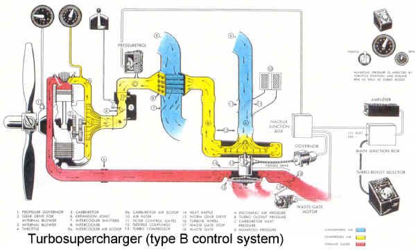
Turbo Control
These exhaust pipes (stacks, manifold, etc.) are rather carefully designed to serve one basic purpose, transporting very hot combustion gasses directly from the combustion chamber to the free air outside the airplane, without letting too much heat, fire, or smoke escape into the engine compartment. Ideally, the exhaust system will minimize the resistance to the flow of hot gases, because backpressure in the pipes and at the exhaust valve will reduce the efficiency of the “scavenging” process (“getting the bad air out”), and reduce the power output of the engine. A few after-market companies have tried “tuning” the exhaust, and while this can improve the net power a bit (a few horsepower at best), most of the claims are grossly exaggerated. Basically, we live with the added backpressure, when a turbo is installed, as it more than makes up for the power loss.
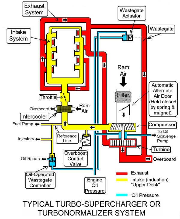
But now we add to the complexity of the exhaust system by sticking a turbine wheel into the flow, and we need some method of controlling the speed of that wheel.
To my knowledge, the only practical method of controlling the speed of the turbine wheels is to split the exhaust gas into two pipes. One pipe goes to the turbine wheel, the other simply exhausts overboard. Left alone, most of the gas would exit via the straight pipe, taking the path of least resistance. But then we add the key component in the control system, the “wastegate.” This is nothing more than an adjustable blocker door within the pipe that does not feed the turbine. When open, it permits the free passage of most of the exhaust gas overboard. The turbine wheel will get some, depending on the relative sizeof the two pipes. But as we close that wastegate door, it obstructs that pipe, damming up the hot gasses, creating more backpressure, and that forces more exhaust through the turbine wheel, driving it faster.
There are several ways to control the movement of that wastegate door. Early military airplanes measured various parameters (including turbo RPM, a trick I’d love to see done now!), fed those signals to large amplifiers (tubes only, no transistors in those days), and used electrical control units to move the wastegate as needed to produce the desired results.
Early general aviation turbo systems sometimes had a simple manual control, just like an additional throttle. The wastegate would be fully open for takeoff, and as the altitude increased, and the pilot wanted more manifold pressure, the”additional throttle” would be added to produce the desired manifold pressure. Various methods of automatic control have been tried, with varying degrees of success.
In the next column, we’ll build that turbonormalized system step-by-step.
Be careful up there!
