


One of the most common places Experimental airplane owners look for performance improvements is the propeller, and many homebuilts go through several props in their lifetime. This is not surprising as propeller design, like many aspects of aircraft design, is an exercise in tradeoffs, but prop design in particular is a black art to many. There are only a few manufacturers of fixed-pitch props for standard aircraft, but quite a few options for Experimentals.
When I bought my Hatz CB-1 biplane a year ago, it was equipped with an older Sensenich metal prop. Gus Milebach, the original builder of the plane, had tried a few different props, starting with a Hegy prop that he said “was a guess when I built the plane.” He then ran a Sensenich 74×54 wood prop for about 20 hours before switching to the aluminum prop from a Piper Colt “for more climb out of a short strip,” though he noted it flew faster with the wood prop.
The plane flew well with the aluminum prop, but I thought it could do better as the engine was well below its rated rpm and thus not developing full power in a full-throttle climb. Also, the old Sensenich 76AM series props were the subject of an airworthiness directive requiring inspection for scratches every 25 hours. There is some debate about whether ADs apply to Experimentals, but it wasn’t a big concern. Checking the propeller should be a part of every preflight inspection anyway, and the prop had been in service for over 50 years and hadn’t failed yet. Still, wood’s inherent damping means it should run smoother. A wood prop is also lighter and it just looks right on a biplane. Gus still had the wood prop and I considered buying it from him, but like him I valued climb performance more than speed. If speed is a priority, a biplane probably isn’t the best choice anyway!
Selecting a New Prop
The Lycoming O-290-D engine powering my Hatz is rated at 125 hp at 2600 rpm. It also has a 5-minute takeoff power of 130 hp at 2800 rpm, but pitching to reach that rpm makes for poor performance at normal cruise rpm unless a variable-pitch prop is used. Climbing at 60 knots, I was seeing 2500 rpm; it would just reach 2600 rpm at full power in level flight, which is about right for a cruise prop. The 65% economy cruise setting gave me a comfortable 70 knots.
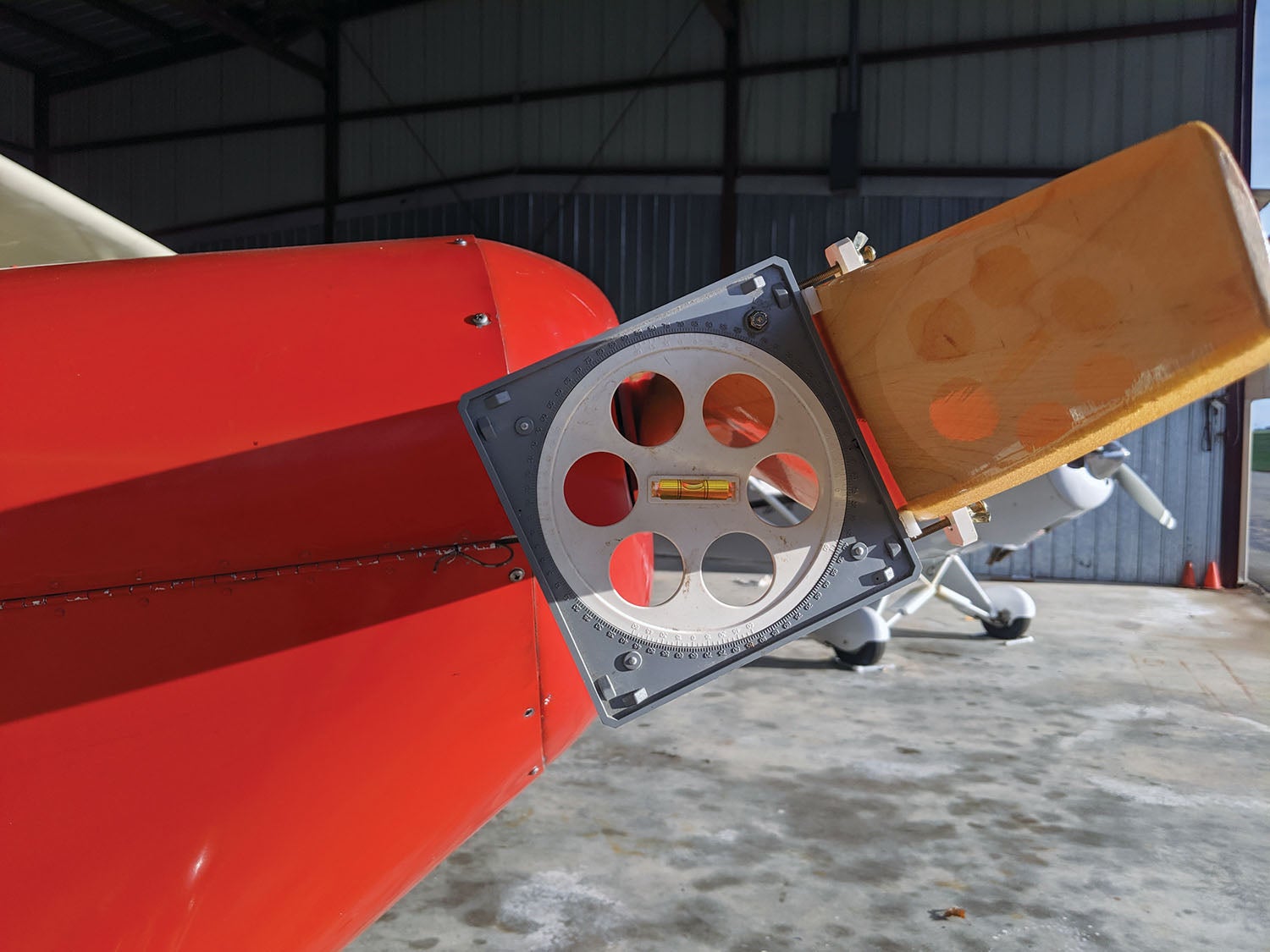
But what was the best pitch? Time to do some research, which often involves reconciling conflicting information from various sources. To complicate things, different prop manufacturers seem to measure pitch in different ways. According to the logbook, it was a 76AM6-2-52, which is 74 inches in diameter and 52 inches in pitch, but when I measured the pitch with a Warp Drive protractor, it came out to more like 49.3 inches. That agreed close enough, as the standard cruise prop for a PA-22-108 Colt was a 74×50, with 74×48 being the climb prop option. While the Colt is a faster airplane (94 knot cruise) than my biplane, it has less power with its 108-hp O-235 engine. When I eventually removed it to mount the new prop, it turned out to in fact be a 76AM6-2-50.
From various internet sources, production airplanes using the O-290-D include the Piper J-5D or Army L-14, which used a 76×44 and the PA-18, which used a 74×47 or 49 (though another PA-18 model apparently used an 80×32, which sounds like the “Borer” props popular with the STOL-plane crowd). The PA-20 and PA-22, which are faster, used a 74×54 or 74×56.
Information on homebuilts is even more nebulous. Looking through old Hatz Association newsletters and searching online forums for reports on Hatzes with O-290 engines, I found a range of propellers used, mostly 74- or 76-inch diameters with pitches ranging from 46 to 54, and a range of cruise speeds claimed. Of course, many homebuilders use whatever secondhand prop is available, which may or may not be the best match.
Asking various propeller manufacturers for a recommendation, I again got a range of suggestions from 44- to 50-inch pitch. There was also a wide range of prices and lead times, from $615 and three weeks from Sterba Propellers to $2750 and six weeks for a certified Sensenich prop, with prices in between but even longer times from other makers. Of course, you don’t need a certified prop on an Experimental. In the end, I decided to go with Sterba both for the price (I could buy and try four Sterba props for the price of one Sensenich) and the lead time. Ed Sterba initially recommended a 50-inch pitch, reminding me that he can (and will, at no charge) rework a prop to reduce the pitch but cannot increase it. However, another Hatz pilot with the same engine as mine said that he started with a 74×50 Sterba prop but found it too much. He had it reworked down to 72×46 in several increments and thought it could still go a little lower.
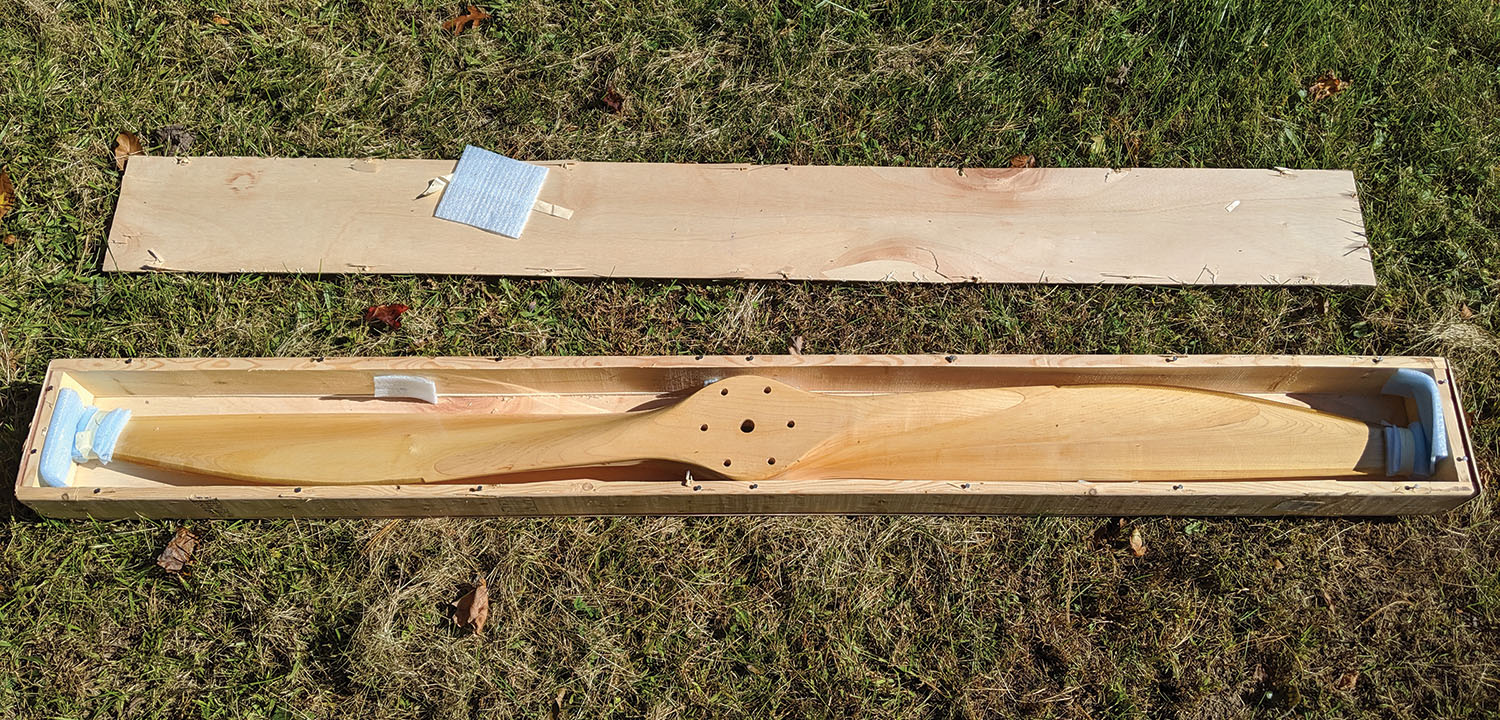
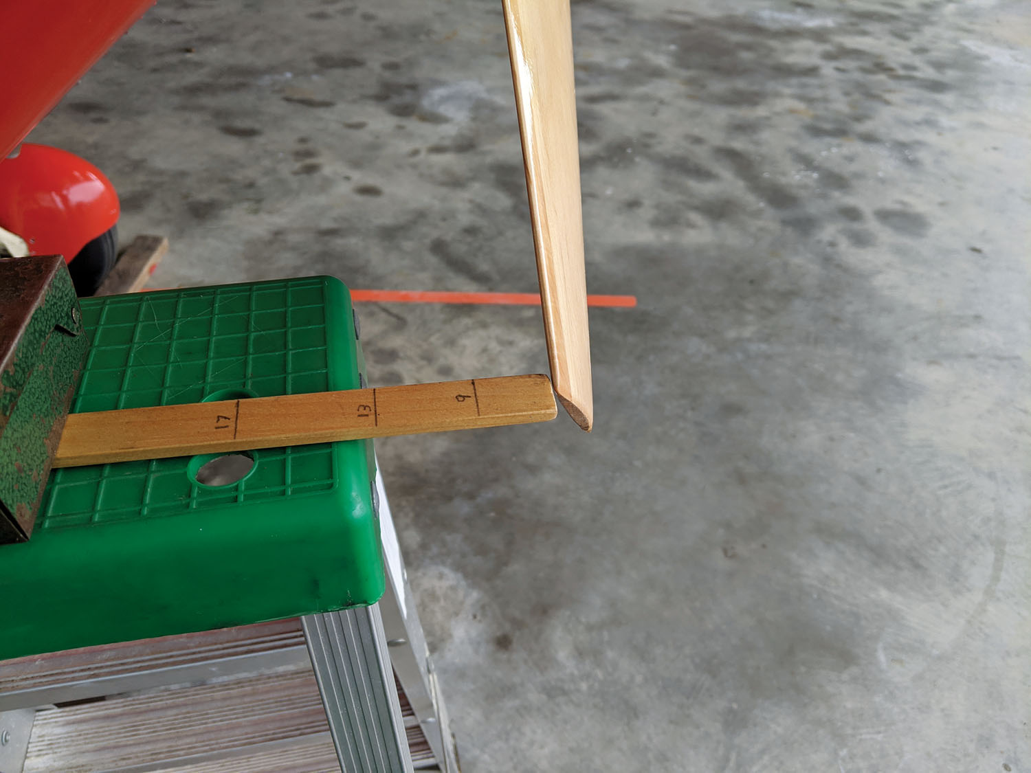
Based on that information and knowing my Hatz is draggier than others with its round cables instead of streamline wires (so I would want more low-end pulling power while expecting it to cruise slower), I decided to start with a 74×47 with the option of further reducing it from there. A month later a wooden crate arrived with a brand new propeller inside. Unlike the metal prop with its flat back, the new prop’s curved rear face made it hard to measure accurately. By sticking blocks to the protractor so it contacted the back face 1/8 inch in from the leading and trailing edges, I got a measurement of about 47¼-inch pitch, which was within tolerance of what I ordered.
A Major Change
The Experimental operating limitations originally issued for my plane said, “Any major modification to this aircraft as defined by FAR 21.93 invalidates the special airworthiness certificate.” Part 21.93, in the FAA’s typically backward language, states that “a minor change is one that has no appreciable effect on the weight, balance, structural strength, reliability, operational characteristics, or other characteristics affecting the airworthiness of the product. All other changes are major changes.”
A propeller change could certainly have an appreciable effect on the operational characteristics of the aircraft! However, the standard template used for new operating limitations today uses different language: “After incorporating a major changed as described in 21.93, the aircraft owner is required to reestablish compliance with 91.319(b) and notify the geographically responsible FSDO of the location of the proposed test area…The aircraft must remain in flight test for a minimum of 5 hours. Following satisfactory completion of the required number of flight hours in the flight test area, the pilot must certify in the records that the aircraft has been shown to comply…”
I had already applied for and received a new airworthiness certificate and updated operating limitations a few months earlier, partly in anticipation of the propeller change but also to return the plane to the Phase I test period to make aerobatics legal. (During Phase II, only those aerobatic maneuvers that were logged during Phase I may be performed, and the original builder never did so.) The new limitations also specified a new test area around my own home field since the builder had lived in a different state. I completed the aerobatics testing earlier in the year; for the prop change I only had to notify the FAA of the change and receive their concurrence on the [same] test area.
Mounting the Propeller
As the new wood prop would have a thicker hub than the metal prop it was replacing, I would need longer bolts. The narrow grip length range of AN bolts makes it essential to select the correct length. The bolts need to be long enough for proper thread engagement in the crankshaft flange bushings, but not so long that the threads will bottom out before the bolt head snugs up. Because of this, some people have used AN76 (MS20073) bolts, which have longer threads than AN6 bolts, but they’re pretty much unavailable nowadays in the sizes needed. Special prop bolts with longer threads are also made, but the available length increments made it appear that one length was too short and the next available longer length would be too long. In the end I ordered AN6 bolts of what looked like the right length and carefully checked them during installation.
A wood prop, unlike a metal prop, requires a front washer or “crush plate” to spread out the bolt loads. Metal props are usually installed without a crush plate, but I had one on mine, where it was serving as the locating plate for a “skull cap” spinner.
Since the test area was a 30-nautical-mile radius from my home field, I waited until the summer fly-in season was over before limiting myself to local flights for 5 hours. I also wanted to do my testing in as near as possible standard atmospheric conditions (59° F) instead of the performance-killing heat of summer.
Testing
To get an accurate picture of the difference, I wanted to fly identical test flights—first with the old prop, then the new—on the same day so the conditions would be as similar as possible. The remainder of the required 5 hours would largely be reliability testing. I would primarily test climb performance as that’s what I was looking to optimize, though I also wanted to check speed and rpm at full throttle in level flight.
To measure rate of climb and determine the best rate and angle of climb speeds (Vy and Vx), the aircraft is flown in a steady climb at fixed speeds and the time to climb a set distance is recorded. This can be done with an altimeter and stopwatch, but using recorded data is easier. GPS altitude typically isn’t accurate enough for this, but I have an older handheld Garmin GPSMAP 60CSx that includes a pressure sensor, giving much better accuracy. The actual altitude recorded is less important than the change in altitude. The plan was to fly a series of sawtooth climbs at 5-knot increments, from just above my 45-knot stall speed to max level flight speed of around 80 knots.
A few days before I was to start testing, a member on the Homebuilt Airplane forum posted that he had written an app to measure engine rpm by listening to the exhaust sound and was looking for people to test it. I contacted him and got an advance copy of the program so that I could verify my tachometer’s accuracy. It struggled with wind noise in the open cockpit but worked well enough for my needs. The released version of the program, Engine RPM from Real-Time Specialties, is now available in the Google Play Store and App Store for iPhone.
Finally, in late October I had an available day with good forecast conditions. When I got to the airport, though, the breeze had picked up, making it less than ideal. I decided to go ahead anyway. With 15 gallons of fuel and GPS and camera recording, I took off and headed south to the shoreline where I hoped the air would be smoother. It wasn’t, but I proceeded with the testing anyway, making a series of climbs and descents at constant (or as near constant as I could hold in the rough air) airspeeds of 50, 55, 60, 65 and 70 knots. I also made a full-power level flight run at what turned out to be 80 knots before heading back to the airport. Trying to hold a precise airspeed, especially in rough air, is extremely fatiguing!
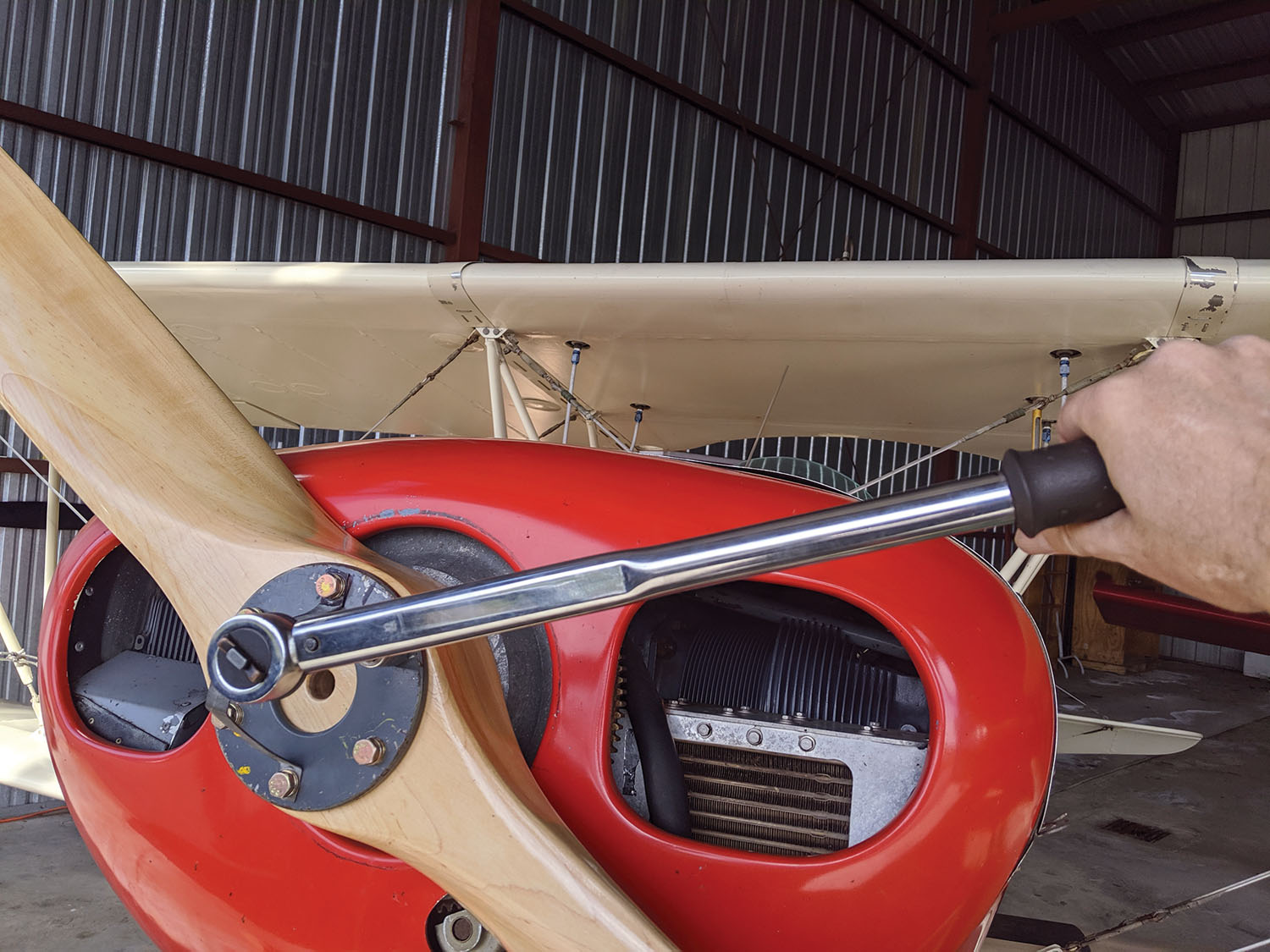
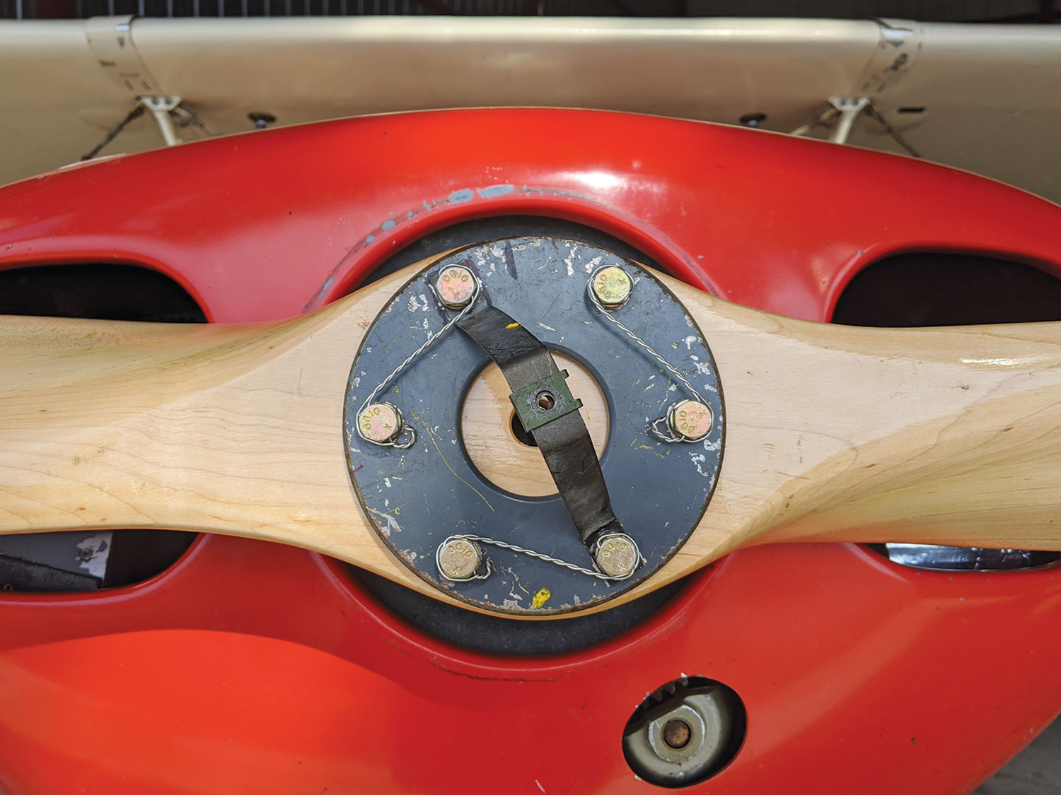
After landing, I removed the metal prop with a friend’s help (it was tight on the bushings and difficult to remove) and installed the new wood prop. The new bolts were a hair too long but an extra washer on each bolt fixed that, then they were torqued in increments to the proper value. Proper torque is especially critical on wood propellers as they are driven through friction between the crankshaft flange and the prop’s rear face, not shear on the mounting bolts. The propeller track must also be checked. Both blades must be within 1/8 inch of each other at the tips, as indeed they were. Finally, after safety wiring the bolts and installing the spinner, I started the engine to check the static rpm. The phone tachometer app showed that the aircraft’s tach was reading around 20 rpm low, which isn’t too bad.
The immediate impression was that the new prop was smoother running, as expected, and responded faster to throttle changes, also expected, as it weighed only 9 pounds versus 24 for the metal prop. The static rpm was about 40 rpm lower, but still within an acceptable range. I then took off and flew the same test series. Fifteen pounds less on the nose made for a noticeable trim change, but the plane was still well within the weight and balance limits. Takeoff and climb performance seemed a bit off, but cruise speed at the same rpm and top speed at full throttle both increased by about 5 knots. Full-throttle rpm, however, was running around 75–100 rpm less than the metal prop at the same airspeeds—an indicator that it was still a bit too much pitch.
After the first flight, the bolt torque on a new wood prop must be rechecked, which requires the tedious task of removing and redoing the safety wires. This I did, then went home and downloaded the data from the GPS and camera.
The data was disappointing. The GPS-recorded tracks were too uneven to draw any precise conclusions due to the rough air, so more testing would be needed. But it confirmed my initial impression that the wood prop gave less climb at all speeds than the metal prop. A couple of days later I tried again, though just with the new prop. Although the air was a bit smoother and the GPS data was better, it still wasn’t good enough for any firm conclusions. The best I could say was that the metal prop performed noticeably better.
To get good data, the proper thing to do would be to fly each test sequence several times and average the data. But not only would this be time consuming (each test flight was around 45 minutes), I wasn’t convinced it was necessary as I had a good idea of what I wanted based on rpm. But since it was OK, if not great, I flew it a few more times over the next few weeks. It was hard to quantify, but it was clear that I had lost takeoff performance; I particularly noticed that it took longer after liftoff to accelerate to my usual 60-knot climb speed, and I was reaching pattern altitude farther along the pattern. Finally, just before shorter days and cold New England weather curtailed my flying, I removed the prop and reinstalled the metal prop. I immediately noticed better takeoff and climb.

Making Adjustments
It was clear that the pitch needed to be reduced, but by how much? Ed Sterba will adjust the pitch at no cost as many times as necessary, but I didn’t want to be shipping the prop back and forth many times with the associated shipping costs and risk of damage. And if pitch is reduced too far, it can’t be increased. Even though the new prop had less pitch, which should give more rpm, I was seeing less. However, the wood prop has a thicker and more cambered airfoil section and a different blade shape, so it wasn’t a straight comparison.
My original goal was to get closer to 2600 rpm, where the engine develops its rated 125 hp in climb, even if it would overspeed a bit in level flight at full throttle. It seemed an increase of 150 rpm would be about right, bringing it up to around 2550 in climb. According to Ed, one inch of pitch is good for about 50 rpm, though others say it could be as much as 100. At 50 rpm per inch of pitch, that would work out to a 3-inch reduction to 44 inches. After talking to Ed on the phone about what I wanted, I packed the prop back into the crate and shipped it off to Florida. A couple of weeks later I had it back, just in time for a spell of cold, snowy weather. I’m not sure if it was my measuring technique or if Ed was being cautious about removing too much material, but measuring it on the bench gave me a figure of 46 inches, which was not as much reduction as I wanted. But that wouldn’t stop me from trying it.
A month later there was a forecast for a good warm day during the week, so I decided to go flying on a long lunch break from work, having reinstalled the altered prop the night before. I didn’t have time for a complete test, and it was again bumpy, but I flew around for a while and did some takeoffs and landings. It was a noticeable improvement; acceleration on the takeoff roll and climb seemed better, but it still wasn’t reaching the engine’s rated 2600 rpm in level flight, much less during climb. I made a few more short flights when weather permitted, but it was another month before I got good weather on a weekend day with enough time to test, swap and test again. Instead of measuring climb rate at different speeds this time, I made multiple climb tests at 60 knots, which is my usual climb speed.

The results were again somewhat ambiguous. I took off into another typical New England winter day (cold and bumpy) and made a full-throttle level run and four climbs from 1000 to 2000 feet before my fingers were too numb to continue. Back on the ground and once my fingers warmed up enough to manipulate the safety wire, I removed the wood prop and put the metal prop back on and repeated the exercise. It was again too bumpy to tell for sure which performed better, but the wood prop was still turning slower while cruise and top speed were still about 5 knots higher.
Could I do better by reducing the pitch some more? Possibly, though the gain might be small; another 100 rpm would only mean another 2 hp, and since the prop is shaped by hand, it’d be all too easy to go a little too far. One inch of pitch is a very small change in terms of the actual material removed, and I might end up with worse performance instead of better. Another option would be to keep the pitch the same, but simply trim the ends to reduce the diameter an inch or two. Ed suggested I do that myself, without risking shipping damage on another round trip to Florida. I resolved to wait until I had another chance to swap props on a good day before making any decision.
Finally, in February I got the perfect day. Not only was it unseasonably warm, but the winds were off the ocean, meaning glass smooth air over the coastline. Instead of testing at different speeds, I did four 60-knot climbs and a full-power run with both props, then just flew around for a while enjoying the beautiful day before going home to analyze the data. This time it was much more consistent. The rate of climb with the wood prop averaged 144 fpm less than the metal prop, but surprisingly it was still turning the same 75 rpm lower as before in climb as well as at full power, where the speed was still slightly higher than the metal prop. Clearly, it wasn’t quite there yet.
Now I had a dilemma: I could send the prop back to Sterba for another adjustment, I could trim a bit from the diameter to bring the rpm up, or I could attempt to rework the pitch myself. Trimming the tips would be easy, but more diameter is usually better, and the issue was too much pitch, after all. The decision was clarified while discussing the options with a friend who said, “Face it—you know you want to take the craftsman approach!”
Yes, I often tend to do things the hard way if it’s more interesting. And just like choosing an airplane, “I want to” can be a perfectly valid reason to do something. I decided to rework the pitch myself, which we will discuss next month in Part 2 of this story.
Updating the Operating Limitations
To get new operating limitations issued with a new test area, you will need to fill out FAA Form 8130-6, Application for Airworthiness Certificate. Since the operating limitations are considered a part of the airworthiness certificate, you will be getting a new one. A new “program letter” is also required, explaining why you are applying for a new certificate, along with a photo or drawing of the aircraft. Not knowing it was required, I initially submitted the application to the FSDO without a program letter, but they kindly provided me with a template to create one with all the required information. Once those documents are submitted, they will process the application and make an appointment to exchange the old paperwork for the new. The regulations don’t seem to specifically require an inspection for an amended airworthiness certificate, but the inspector may want to do one anyway. In this case he did, in part to introduce a new inspector with mostly airline background to smaller airplanes and Experimentals. It was a cursory inspection; we exchanged the paperwork and I was ready to go.
It’s worth making sure that you know what the changes in your operating limitations will be before starting this process. In many cases the new limitations will be less restrictive than the old. For example, my original limitations (issued in 1987) not only prohibited major changes but also stated, “No operation shall be conducted over densely populated areas or in congested airways except for takeoffs and landings.” The new limitations update the “major change” restriction, and the densely populated area restriction now adds, “unless sufficient altitude is maintained to make a safe emergency landing,” thus giving a bit more freedom.
On the other hand, some older operating limitations are very loose in their requirements and getting yours updated may make yours more restrictive. The current language can be found in the latest edition of FAA Order 8130.2.
—D.H.
Dana Hague soloed at 16 and has been messing around with the low and slow side of aviation ever since. An aerospace engineer by education and mechanical engineer by trade, he’s been taking things apart almost since birth and usually manages to put them back together again. He’s owned and tinkered with a variety of homebuilts over the years and currently flies a Hatz CB-1 biplane.
This article originally appeared in the October 2020 issue of Kitplanes magazine.
For more great content like this, subscribe to Kitplanes!

Regarding the safety wiring of the Hatz biplane’s prop….. looking at the foto in the article, it appears the top right safety wiring is wrong. It appears to be the reverse of the others.
That caught my eye also. It appears that those two would simply “unwind” the wire if they loosened, at least for a half turn or more. That would be safety wire for a left-handed threaded bolt. But otherwise, a very detailed article!
Meta; / Wood / and now Carbon….. 🙂
Yikes, the safety wires on two of those bolts are running the wrong way.
Also, just to note, it’s really fastener tension that’s important and torque is an imperfect measure of that. Were the torque values to get the correct tension referenced from dry clean threads, oiled threads? If there’s a burr you missed, that could result in proper torque, yet insufficient tension.