


")


")


In my previous column, we explored a bit of the history of supercharging, some of the many variations, and some of the reasons for it. We touched lightly upon the turbochargers, which make it possible for an aircraft engine to produce a manifold pressure greater than ambient pressure,and thus more power. We also mentioned the turbonormalizers, which make it possible for an engine to maintain sea-level horsepower to some much higher altitude, usually 20,000 feet or more.
In reality, of course, the turbo systems themselves are virtually identical,with few differences between the “turbosupercharger” and the “turbonormalizer.” The only real differences are the wastegate controller (there are several basic types, and many variations), and the settings for the pressures to be used. From this point on, I’ll just call them all “turbo systems” unless there is something specific to one or the other.
In this column, I’d like to dissect this very neat (and sometimes much maligned) system, component by component, and perhaps take a bit of the mystery out of it for some. Why “much-maligned”? Because a lot of the early ones were badly designed, some to the point of being dangerous. Some imposed significant additional workloads on the pilot, and it was easy to use them improperly.
Modern turbo systems have come a long way from those early days. If you were turned off by some of the stories before, I think it’s time to take another look.
You will find some minor differences between the system I describe here and some of the turbo systems “out there” but it should be pretty easy to figure those out. The following discussion is loosely based on the “Whirlwind” turbo installation as done by “Tornado Alley Turbo” (hereafter TAT) in Ada, Oklahoma. (This is the system I had installed on my own Beech Bonanza.) I’ll try and identify the exceptions as we go along, but this is really intended as a broad, general look at the mechanical aspects of turbos.
Dissecting the Turbo System
Here is the schematic diagram that appeared in the previous column, showing the full installation again:
Click on the graphic above for a higher-resolution version in a separate browser window. You might find it helpful to keep it open for ready reference as you read the remainder of this article.
This was originally an old black-and-white drawing, which I cleaned up and colorized. It is a good “generic” schematic, but does not accurately reflect the exact layout of the TAT system. In the remainder of this article, I will extract each component from this diagram, piece by piece, and go into some detail. Finally, I’ll explain what all these parts are doing during various phases of flight.
Induction and Exhaust Manifolds
These two pictures illustrate the normal induction and exhaust manifolds found in most “flat six” engines. (There are variations, but they’re not important here.) Teledyne Continental Motors (TCM) numbers the cylinders starting with #1 from the right rear as shown here, while Lycoming starts at the left front, so I have not numbered them at all.
The induction manifold is very simple…at least that part of it between the throttle and the cylinders. Whether the engine is carbureted or fuel-injected, turbo’d or non-turbo’d, intake air passes through the throttle body and then it splits into two equal-sized “log runner” assemblies, with a “riser” coming off the main runner to each cylinder. On most of the Continentals, this is an excellent intake system, which provides almost perfectly equal air to both sides of the engine, and to each cylinder. (Yes, this is somewhat contrary to popular belief!)
There is some mystery over the induction crossover tube at the front of the engine, with no one quite knowing what it does, or why it’s there. I think of it as the mechanical equivalent of the human appendix. Some say it adds a little bit of power at some settings, and takes it away at others, some say it has something to do with resonance. If the real experts don’t know, who am I to guess? In any case, it comes with the engine, turbo or not, at least on the Continentals. Perhaps some astute reader will have more on this?
On the non-turbo’d engine, the exhaust system is really simple, one pipe comes out of each cylinder and flows into a main pipe on each side, which conducts the hot gasses overboard. In some engines, there are “heat muffs” around one or both exhaust pipes to extract some heat for cabinheating and/or for carburetor heat on those engines so-equipped. These are another form of heat exchanger, designed to transfer heat from one gas stream to another, without actually mixing them. Fuel-injected engines do not normally have carburetor heat, as they are far less susceptible to induction system icing.
In order to spin a turbocharger, all the exhaust piping comes together in a “wye” (clever technical term for a Y-shaped fitting), and the resulting single pipe goes right back into another wye that splits it back into two flows again. One of these pipes will go to the wastegate, the other to the turbo. If the wastegate door blocks its branch of the system, then all the exhaust gas must go through the turbo. On the other hand, if the wastegate door is open, most of the exhaust is simply dumped overboard (taking the path of least resistance), with only a small amount going through the turbo.
In the TAT system, the exhaust from the right side of the engine simply wraps around the back of the engine to join with the left side exhaust. This neatly leaves room on the right side for the intercooler. Both exhaust streams “wye” apart again, one pipe to the wastegate, one to the turbo. In some systems, the exhaust streams will remain separate, each leaving through its own exhaust pipe,in others it will “wye” back together again, to leave through one large exhaust pipe. Still other systems employ two small turbochargers instead of one big one, each driven by the exhaust from one bank of cylinders.
The “Upper Deck”
This mysterious term is simply a nickname for that part of the induction system that is between the turbocharger’s compressor and the throttle plate.(The portion of the induction system downstream of the throttle is cleverly known as the “lower deck.”)
The pressure in the upper deck area is usually regulated by the controller,and can be quite independent of the manifold pressure in the lower-deck portion of the induction manifold. In the TAT system, upper-deck pressure will always be regulated to about 33 inches, provided there is enough energy from the exhaust to drive the turbine. Because the intercooler creates a little resistance to the flow of air, the air pressure after the intercooler will be as much as two inches less than the compressor discharge pressure.
It is very important that you mentally separate the lower deck (downstream from the throttle) from the upper deck (upstream from the throttle). Completely different things take place in these two areas of the induction system at anything less than full throttle.
The Turbo Itself
Here is a rough schematic of the turbocharger itself, and a photo of atypical turbo:

As you might suspect from the picture on the right, the actual air passages and air flows are very curved and smooth, and the tolerances very tight in this most critical component, which is capable of turning in excess of 100,000 RPM. The blades in each part of this unit are shaped differently, with the turbine looking something like an old-fashioned waterwheel. The hot exhaust gas strikes those blades, and drives the turbine. On the other hand, ram air enters at the center of the compressor, and is flung outwards by centrifugal force.
Oil System
The oil system associated with the turbo system is a very simple lubrication and control system.
The bearings in the center section of the turbocharger are quite critical,and not only need an uninterrupted supply of full engine oil pressure for lubrication and cooling, but a scavenge pump is also needed to literally suck the oil out (“negative pressure” for the purists) as any back pressure would reduce the efficiency of the oil flow, and might also allow oil to leak through the bearings to either the compressor or the turbine. This scavenge pump is a very important component, a significant part of the turbo conversion. It is cleverly gear-driven by the engine off the starter gearing in the TAT turbonormalizer. In some of the Lycoming systems, it’s a separate gear-driven pump mounted on a spare pad in the accessory section. In most TCM factory-turbocharged engines, the scavenge pump is piggy-backed onto the engine’s regular oil pump and shares a common drive shaft.
Sometimes you will see a turbo system emit a small puff of oil smoke from the exhaust on starting, and this is probably where it comes from. Any oil left in the turbo at shutdown may pool and leak slowly past the seals into either side of the turbo unit, to be forcibly ejected at the next engine start.
It is important for the engine oil to be properly warmed prior to pulling significant power from any engine, and even more important for the turbo bearings in a turbo’d engine. I’ve always been just a little uncomfortable with Lycoming’s advice to take off as soon as the engine will accept full throttle without faltering, or “as soon as the oil temperature needle starts moving.” I sure didn’t push things quite that much in my engine before the turbo installation, and I sure won’t now, thank you very much. But that’s a personal opinion.
Intercooler
The intercooler is the simplest device in the system, with no moving parts:
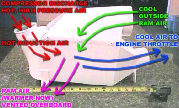
It is simply a radiator (or heat exchanger) designed to transfer heat from one airstream to another. The two streams are kept separate from each other, but pass inside and outside a common system of fins and tubes. Hot compressor discharge air, heated by compression, passes through this device, and is cooled a bit. Ambient ram air comes in, passes through the intercooler, picks up some of the heat from the induction air, and is promptly dumped overboard.
Wastegate Controller and Wastegate Actuator
The biggest differences you’ll see between one turbo system and another is the controller. There are a bewildering variety of them, each designed to control the upper deck pressure in the way the designer felt was best.
A few installations have no controller at all, and the wastegate is either fixed at some setting to serve the purpose, or is manually controlled by the pilot (using an additional throttle-like cockpit control, or occasionally a complex linkage to the main throttle control). As usual in aviation, all are compromises in some way, and all have their advantages and disadvantages. But a turbo system without an automatic wastegate controller adds greatly to pilot workload, and seems like a really bad idea to me.
TAT has wisely chosen to use the very simple “Absolute Pressure Controller” (APC), which strives to maintain a constant manifold pressure of about 31 inches. In order to do this, the controller is set to maintain an upper-deck pressure of about 33 inches to overcome the pressure drop across the intercooler and throttle body. The controller “setpoint” is adjusted by simply changing the mechanical compression on the spring load in the controller with a screwdriver. The APC does an excellent job when the throttle is wide open, but less so at partial throttle because the turbo may still be working hard to produce an upper deck pressure that is not needed. For example, if you set 15 inches MP for descent, the APC still commands the turbo to produce 33 inches in the upper deck. Many of us believe that full throttle operation is the only way to fly this setup anyway (at least until it comes time to land), so this is not a problem. On the other hand, the turbonormalized engine is not the best choice for a pressurized aircraft, as the higher the upper deck pressure,the more pressure available to the cabin, which will maintain a lower cabin altitude.
The Variable Absolute Pressure Controller (VAPC) is very similar to the APC, but instead of a screwdriver setting (or in addition to it) there is a mechanical linkage to the throttle. If you reduce the throttle to some low MP setting, the linkage will back off on the setpoint, effectively telling the turbo to quit working so hard when it’s not needed. This type will often be found on pressurized aircraft with turbos. These engines typically run a much higher MP, so “giving the turbo a break” is more important.
There are other variations, such as a “slope controllers” and”pressure ratio controllers” (PRC) that are used in some installations to vary the upper deck setpoint with altitude in some fancier way. For instance, Mike Busch writes:
My T310R uses a combination of APC and PRC. Up to critical altitude (16,000 feet MSL in my airplane), the APC maintains constant upper-deck pressure (UDP) of about 34 inches. Above 16,000 feet MSL, the PRC takes over and reduces UDP as the airplane climbs to maintain a constant 2.2-to-1 ratio of UDP to ambient pressure. The purpose of the PRC in this installation is to prevent turbocharger overspeed at altitudes above critical altitude by limiting the compressor discharge-to-inlet pressure ratio to the value it has at critical altitude.
The TAT turbonormalizer system doesn’t have this limitation. The turbospeed was checked during the STC altitude flight testing, and will not overspeed under any circumstances.
Whichever controller variation is employed, the basic construction is essentially the same.The wastegate controller consists of a spring-loaded poppet valve, similar to those in traditional hydraulic control valve systems. It has a vacuum-sealed reference aneroid (chamber) hooked to a spring with adjustable tension. Air pressure from the upper deck works against the aneroid and the spring, which moves the hydraulic poppet valve, porting engine oil as needed to control the oil PRESSURE to the wastegate actuator.
That oil pressure, in turn, moves a small hydraulic piston in the wastegate actuator over a distance of about two inches, and this movement controls the position of the wastegate door, which diverts the flow of exhaust gas to the turbo or away from it, driving the turbo faster or slower as needed to raise or lower the upper-deck pressure.
If all this sounds a bit Rube Goldbergish to you, you’re not alone. But there are good reasons for all this monkey motion, and the system works remarkably well.
Notice the engine oil pressure first flows through the wastegate actuator, then on to the controller. Seems backwards, somehow, right? In this case, the controller acts as a dam, creating or relieving backpressure in the line. In case you’re wondering, it doesn’t affect the main engine oil pressure very much,because these control lines are much smaller, and the tiny bit of”leakage” used for control will not affect the main engine oil system.
Pressure Relief Valve
Just in case the control system malfunctions, there is an additional device to provide protection from overboost.
This is a simple mechanical relief valve, totally stand-alone, not dependent on any other system. It’s just a tin can with a spring-loaded valve inside, with an adjustment to pop open if the actual upper-deck pressure rises to some limit, generally several inches above the setpoint at the controller. Normally, this “popoff” valve remains closed at all times, only opening (as shown in the inset) for overpressure. To my knowledge, all turbo’d engines have this safety feature to protect from a gross overpressure due to failure of thecontrol system.
Injection Nozzle Aspirators (Breathers)
Look at this photo of a turbocharged engine:
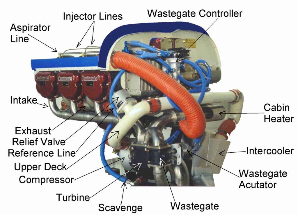
Note the air line from the upper deck to the injectors. Why send air to fuel injectors?
It turns out that just injecting a stream of liquid fuel into the intake port is not a very good way to do it, because there isn’t time for the fuel to atomize. On a non-turbo’d engine, each injector will have tiny holes to the ambient air at the point where the fuel is moving the fastest. There are tiny screens to keep trash out. The high-speed fuel creates a suction, which draws in ambient air. That is mixed with the fuel right in the injector and the intake port, producing a mist of fuel going into the combustion chamber, for better combustion.
On the turbo’d engines, supplying ambient air to the injectors doesn’t work very well, because ambient pressure can be so much lower than manifold pressure. (If you tried using normally-aspirated injectors on a turbocharged engine, fuel would squirt out the injector air holes instead of air being sucked in.) Instead, we steal the pressurized air from the upper deck (which is guaranteed to be greater than manifold pressure), and pipe it to the injectors. If you examine any injected, turbocharged engine, you will see a fairly extensive system of “upper-deck reference lines” for this.
How It All Works Together
Now that we’ve looked at the individual parts of the turbo system, I’d like to run through the various phases of flight from the standpoint of what is happening in the system. This is NOT intended as an operating manual! I’ll get into TECHNIQUE in the next column. This is simply a review of what all the parts are doing during some sort of “normal operation.”
Not Running
With the engine at rest, the spring in the CONTROLLER drives its poppet valve closed trying to increase the oil pressure in the actuator. Of course, with no oil pressure at all, nothing happens. Since there is no oil pressure yet, the spring in the wastegate ACTUATOR drives the wastegate door open in our drawing. I know, who cares, right? Hey, we gotta start somewhere!
Engine Start
Now, the moment we start the engine, and run it at low RPM (see sidebar please) the oil pressure builds up in the engine oil system and in the turbo bearings, then against the wastegate actuator, driving it fully closed. Why fully closed? Look at the diagram of the entire system again. The controller’s poppet valve is still closed, because the upper-deck pressure is not yet high enough to open it. The controller always WANTS a full 33 inches of pressure in the upper deck at all times, and will stubbornly remain closed (trying to raise the control oil pressure) until it gets 33 inches. That closed control valve traps the engine oil pressure in the control line, forcing it to rise to the full engine oil pressure, which drives the wastegate actuator closed against the spring. When the wastegate closes, it backs up the exhaust gas in the pipe where the wastegate is located, which diverts all the exhaust through the turbine. That spins the turbocharger up, but since there is so little exhaust gas at idle RPM, it’s probably not fast enough to produce full pressure in the “upper deck.” On the other hand, some systems may do so, for only about 3 inches additional pressure is needed. Remember, the turbo is sucking in ambient air at 29 or 30 inches (at sea level), and only has to work a little.
Now, if you’ve read the column on MP, you’ll understand that at idle, the pressure downstream of the throttle (on the engine side) is very low (high suction), because the throttle plate at idle is fully closed, and the pistons are desperately trying to suck air past it. The air in the “upper deck” at idle is probably pretty close to ambient, plus or minus whatever effect the compressor is having.
To beat on this horse a little more, it may be helpful to remember that we are dealing with four different air pressure areas, and three different temperatures in the TAT turbo system.
First, and most obvious, ambient pressure and temperature (OAT).
Second, a slightly different pressure occurs after the air filter, before the compressor. This pressure is usually less than ambient, because the entire system is “sucking” air in, and the filter is a slight impediment to the free flow of air. At high indicated airspeed, the “ram effect” will overcome this to some degree, and on very well designed systems, ram air will more than compensate for the filter loss. There may be a tiny difference in air temperature due to the pressure change, but this can be overlooked.
Third, the “upper deck pressure” and “compressor discharge temperature” (CDT) occurs after the compressor, but before the throttle plate. This is the air pressure regulated by the controller. This hot upper deck air is cooled by the intercooler, giving us our third temperature, “Induction Air Temperature” (IAT).
Finally, there is the manifold pressure the pilot sees on the MP indicator. This is the pressure after the throttle plate but before the intake valves (i.e., the “lower deck”). On those aircraft equipped with Carburetor Air Temperature (CAT) gauges, it will be measured here.
Runup
At some point, as we increase the throttle setting (allowing the engine to suck more air in, develop greater power (increased RPM), increase exhaust flow, drive the turbine faster) the air pressure in the upper deck will hit the setting that triggers the wastegate controller to say “okay, that’s enough.” That upper-deck pressure will drive the poppet valve open just enough to let a little oil trickle out of the control line, which drops the oil pressure at the wastegate actuator. That allows the wastegate to open a bit, allowing some exhaust gas to escape through the other pipe (bypassing the turbo), thereby depriving the turbo of some of the driving force. The turbine (and the compressor) slow a bit, and the upper deck pressure drops back a tiny bit. In stable conditions, the system will quickly stabilize at a point where just the right amount of oil is bleeding by the controller, just enough exhaust is driving the turbo, and just enough upper deck pressure is maintained.
With any partial throttle setting, the manifold pressure in the engine (downstream of the throttle) will always be lower than the upper deck pressure. Even with a fully open throttle, it will be very slightly lower, due to the resistance of the intercooler and a tiny bit of blockage by the throttle plate thickness. The manifold pressure you read in the cockpit is, of course, sensed downstream from the throttle. You cannot measure the upper deck pressure without special test instruments. However, at full throttle, you can assume it’s about 2 to 3 inches above the manifold pressure you see.
One of the many nice things about a turbo is that the spring tension adjustment in the wastegate controller can be tweaked a little, just enough to bring the MP up enough to make up for the loss of pressure due to the intercooler, the filter, and the kinks and bends in the system, and return the engine to the full power the manufacturer intended and specified. For this reason, a properly set controller and proper use of the mixture control means that you take little or no “hit” in the horsepower department at sea level, contrary to popular belief.
Takeoff
Okay, runup complete, we take the runway, and open the throttle for takeoff. We don’t worry about overboosting with the turbonormalizer, because the system will maintain about 33 inches of pressure in the upper deck, and the manifold pressure will be about two inches less due to the intercooler. Under no circumstances can the manifold pressure exceed the upper deck pressure, of course.
Let’s talk about this act of opening the throttle. Many pilots will do that very gingerly, afraid of damaging the turbo, or the engine. While I don’t like “yanking” any control around in an airplane, this can be carried too far, in my opinion. While some may say, “well, it doesn’t hurt,” that may not be true. The longer you sit there at high power with no cooling airflow,the hotter that engine is getting. I have no beef with taking the engine up to some fairly decent power setting, doing a final quick check of the engine instruments, then getting the rest of the power applied in a fairly expeditious fashion. Some will hold the brakes during this “engine check,” but I’d just as soon let the airplane start its roll while this is going on, as that will attain a cooling airflow sooner (and get you out of the way of the next airplane). Bluntly, once you are comfortable in any airplane, if you’re not capable of controlling the airplane during the early takeoff roll while doing a quick check of the engine instruments, you probably ought to find another line of work, or another hobby. I’m not referring to beginners here, or to those flying a strange airplane for the first time, or other special conditions like a short runway.
But let’s get back to what the turbo system is doing. On the turbonormalized engine, as you bring the power up, remember that wastegate is initially closed,as the controller wants about 33 inches. That is BARELY above ambient, at sea level, IN THE UPPER DECK. As the turbo speeds up, it will provide that 33 inches of upper deck pressure very early, well before you see significant MP on the cockpit MP gauge. That means that the moment you hit full pressure in the upper deck, the system will not allow the turbo to run any faster, no matter how much throttle you give it. As you further open the throttle, the wastegate will open up to keep that constant 33 inches. It is important to realize that the throttle is NOT directly controlling the turbo (unless, of course, your system uses a VAPC controller with its throttle linkage).
There may be a slight lead and lag in the system as the various devices move in response to each other, but for all practical purposes, the wastegate simply moves to keep the same upper deck pressure.
In summary, as you apply takeoff power with the throttle, the following sequence of events occurs:
- The throttle plate moves away from nearly closed, allowing more air to get sucked into the cylinders by the pumping action of the pistons,
- The fuel control unit responds by pouring more fuel into the system, producing more and more power,
- The additional exhaust (wastegate still closed, remember) spins the turbo, which spins the compressor, which pumps up the pressure in the upper deck.
- As soon as the pressure in the upper deck hits the preset value (just barely above sea level pressure if we’re talking about a turbonormalized engine), the controller starts letting oil pass, dropping the oil pressure in the actuator line,
- With the reduced oil pressure at the actuator, the spring in the actuator drives it towards the open position, dumping more exhaust overboard, dropping the exhaust pressure in the pipe to the turbo, maintaining the same turbo speed (roughly).
Climb
Now, let us suppose we don’t touch a thing after takeoff. Just let the engine run “wide open,” throttle, prop, and mixture all the way in.
Think for a moment, and see if you can predict what all those little thingies in that engine compartment are doing as you climb.
First and foremost, of course, ambient pressure slowly drops with altitude. At 5,000 feet MSL, ambient pressure will be about 24 inches, at 10,000 feet, about 19 inches, and at 18,000 feet, somewhere around 15 inches (the classic “one inch per thousand feet” is only approximately correct below 10,000 feet, and it’s less than that above 10,000).
But that upper deck controller still wants 33 inches! What does it do? As the ambient pressure drops, the engine wants to make less power, and less exhaust, which would, without intervention, reduce the upper deck pressure. But our little controller senses that drop, blocks the flow of engine oil through it, which raises the oil pressure in the oil line to the actuator. That drives the wastegate a bit more closed, which forces more exhaust through the turbo, speeding it up, bringing our upper deck pressure back up to 33 inches. Since the throttle is still wide open and there is no barrier (except the intercooler) between the upper deck and the intake manifold, the actual MP reading will show about 31 inches, and will stay there to the critical altitude, somewhere above 20,000 feet MSL.
At the higher altitudes, the turbo must work harder to bring that low ambient pressure up to the full desired upper-deck pressure. To work harder, it must take more and more of the exhaust gasses, and guess what that does to the temperature of the exhaust gas driving the turbine? Yup, you got it, it gets hotter as you climb. How hot? Well, the turbonormalizer TIT (Turbine Inlet Temperature) may show around 1,200°F or less during a sea level full rich takeoff. In the flight levels, at very high power, with the mixture leaned to peak TIT, it may approach or even exceed the maximum for the turbo (1,650°F on my system).
In general, for any given horsepower, you’ll see much higher TITs (100° to 150°F, same HP) with the TSIO and TIO engines (7.5:1 compression ratios) than you will with the turbonormalized engine (8.5:1). The reason for the lower exhaust temperatures is that the higher compression ratio allows the exhaust gases to expand more during the expansion stroke. This expansion will cool the exhaust flow that leaves the combustion chamber.
In some of the TIO/TSIO engines, the turbocharger’s turbine rotor is made of a different alloy (Inconel), and this allows greater operating temperatures, up to 1,750°F.
We said before that each system has its advantages and disadvantages, and in the operating temperature department, the turbonormalized system has the clear advantage. Only when there is an overriding need for higher manifold pressures will the TIO/TSIO engines be “better,” as in the need for cabin pressurization or greater power.
The TIO/TSIO engines suffer here, because the higher temperatures over the long term affect the integrity of the steel used in the turbo and in the exhaust plumbing. At and above about 1,600°F or 1,650°F for very long periods of exposure,these exhaust components may start to turn brittle, leading to early replacement and higher costs. Not a good thing.
A word about the “altitude-compensating” fuel pumps. To my knowledge, they are not used on any of the normally-aspirated engines except the IO-550 series. This pump has a pressure-sensing device (an aneroid), which measures ambient pressure and reduces the fuel output as altitude increases. In theory, it is supposed to produce a full rich mixture from sea level to about 3,000 feet, and above that it is supposed to lean the mixture by about one gallon per hour per thousand feet of altitude. It’s fine in theory, this produces a “better” mixture at the higher altitudes, and when properly set up, little or no manual leaning is required for high altitude takeoffs. Somehow, “it don’t hardly seem natchural” to me, but I suppose I’m a bit of dinosaur on this one. Many of them are not properly set up, so a bit of experimentation during a normal full-power climb is in order, with adjustments at the fuel pump by your mechanic as needed until it is right.
This pressure-sensing pump is used almost universally on the turbo’d engines. However, since the turbo’d engine maintains sea level power to higher altitudes, the air reference for the fuel pump is tied into our old friend, the upper deck, giving a more accurate mixture setting.
In either case, the pump fuel pressure output responds to changes in the reference pressure, decreasing fuel flow as the reference pressure drops.
The actual results from this aneroid-controlled fuel pump are a little crude. It is not capable of precise control, so depending on just how well it is setup, you may need to occasionally tweak the fuel flow a bit with the mixture control, to maintain the desired temperatures (TIT and CHT). We’ll get into that more next time.
Cruise
At cruise power, the upper-deck pressure should still be about 33 inches, and the MP indicated in the cockpit will be whatever you set with the throttle. There are exceptions to this, however. For example, if you’re high enough, and you pull the RPM or the mixture back too far, you’ll reduce the mass airflow from the combustion process, and there may not be enough to drive the turbo, even with the wastegate fully closed. Even at full throttle, you’ll see the MP drop, along with the upper deck pressure. (This is known as “bootstrapping.”) In this case, you’ll have to put another log on the fire (enrich the mixture), or run the RPM up a bit, until you get the desired MP again.
The Future
There are persistent rumors of a number of improvements in store. Chief among them is an electronic ignition system that is far superior to anything in any engine (car or aircraft) today. It will look directly at each combustion event, and modify the spark timing as needed for the succeeding event. This will produce the ideal pressure event for best power, regardless of power settings, RPM, ambient pressure/temperature, or fuel octane. There is every reason to believe this system will allow all our aircraft engines to run at full rated power on 94- to 98-octane fuel, with NO lead. That will solve the aviation fuel crisis overnight.
Another nice thing to have would be an electronic turbo controller. This could be programmed for optimum operation in all conditions. There have been several attempts at these, but the certification issues are a nightmare. Unison is rumored to be working on one. Atlantic Aero had a prototype at AOPA a couple of years ago. Apparently TCM is also working on one of these. GAMI has a prototype electronic wastegate controller built and being tested. The details are not public for any of these systems, but there should be some real benefits, if the FAA doesn’t get in the way too much.
In my next column, I hope to get into real operations, and some new and more scientific ways of operating these engines. Simpler ways, too!
Be careful up there!
