In the April issue of Aviation Safety, we explored the theories of generating lift from Bernoulli and Newton, and how neither of them alone fully explains how airfoils work. Bernoulli’s basic understanding of low pressure above an airfoil is correct, but the math is wrong and his assumptions are faulty. He also doesn’t explain inverted flight. Meanwhile, Newton has a decent handle on using angle of attack to generate lift and his Third Law— every action has an equal and opposite reaction—tidily handles inverted flight, but he has little to offer us in explaining low pressure above the airfoil.
The closest aerodynamicists reportedly have gotten to a unified theory of how lift is generated involves combining the two, and adding an understanding of how air is deflected when an airfoil passes by. Debating these theories is great for the late-night dorm room session, but once we have an understanding of their strengths and shortcomings, how do we put them into practice? And can we leverage the differences between them to more precisely fly our airplanes?
Quick Review
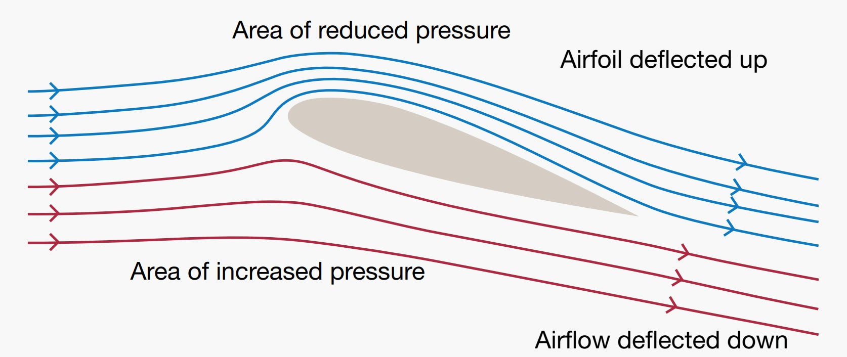
The sidebar below is adopted from the April issue as a refresher and a way to drag us closer to that elusive unified theory. The punchline is that both theories are correct, as far as they go, but sometimes aren’t correct at the same time. This mostly has implications when we’re nibbling at the edges of a theory’s operating envelope. The diagram over there nicely combines the two theories.
For example, air flowing under the wing depicted by the red streamlines exert pressure, deflecting the wing up. In the bargain, that same air is deflected downward—downwash—which helps create ground effect. On top of the wing, basically the opposite is happening. Thanks to the airfoil, an area of reduced pressure exists in the air flow, depicted by the blue streamlines, “vacuuming” the wing into the air and adding to the downwash.
As we noted in April, here’s what the FAA’s Pilot’s Handbook of Aeronautical Knowledge, FAA-H-8083-25B (PHAK) has to say about the contributions of Bernoulli and Newton toward our understanding of how lift is generated:
“Applying Bernoulli’s Principle of Pressure, the increase in the speed of the air across the top of an airfoil produces a drop in pressure. This lowered pressure is a component of total lift. The pressure difference between the upper and lower surface of a wing alone does not account for the total lift force produced.
“The downward backward flow from the top surface of an airfoil creates a downwash. This downwash meets the flow from the bottom of the airfoil at the trailing edge. Applying Newton’s third law, the reaction of this downward backward flow results in an upward forward force on the airfoil.”
In April, we noted that aerodynamicist Doug McLean told Scientific American that he settled on four necessary components to generate lift in his recent book: “a downward turning of the airflow, an increase in the airflow’s speed, an area of low pressure and an area of high pressure.”
“They support each other in a reciprocal cause-and-effect relationship, and none would exist without the others,” his book is quoted by SA. “The pressure differences exert the lift force on the airfoil, while the downward turning of the flow and the changes in flow speed sustain the pressure differences.”
In other words, lift generation is a dynamic event, with interdependencies involving airspeed (power, or thrust if you prefer) and angle of attack (pitch). It’s both repeatable and predictable for a given airfoil, which means any time we want to fly at a certain airspeed or in a certain configuration, there’s a pitch and a power setting for it.
Pitch Plus Power
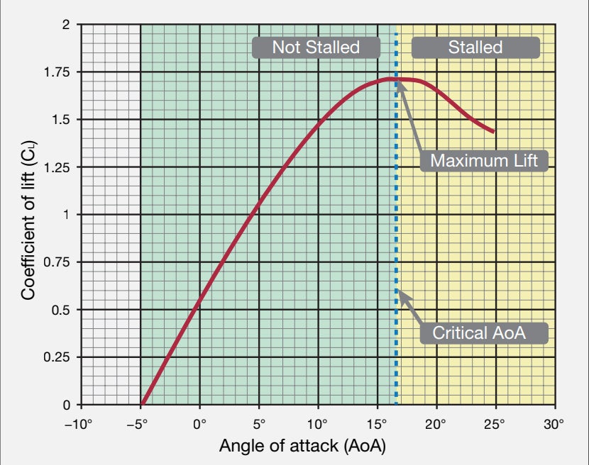
The phrase “pitch plus power equals performance” isn’t a new one, but its simplicity sometimes causes us to gloss over how we measure and juggle the two variables to achieve desired performance. One way is with an angle of attack (AoA) indicator, which may be required aboard some airplanes. For most of us, AoA is both optional and desirable. Over the last few years, regulatory burdens making AoA indicators rare aboard personal airplanes have been eased, and the devices are much less expensive to acquire and install, and more popular than ever. But they are most effective in low-speed/high-AoA situations.
The rest of us can obtain the same basic benefits of an AoA indicator by establishing the pitch and power settings needed to obtain the desired performance. We get the pitch information from the attitude indicator, and engine instrumentation tells us if we’ve established the desired power settings. The only trick is we need to do some testing, write down the results, verify them and then use them. It’s not rocket science, and some of the testing we’d need to do, anyway, with a newly installed AoA indicator.
Writing It Down
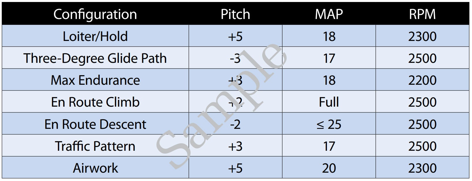
The table below presents a sample guide for establishing seven different everyday configurations and starting-point pitch/power settings for a normally aspirated piston single with a constant-speed propeller. It’s a sample because the values shown are more or less plucked from thin air; they haven’t been tested, but should be in the starting-point ballpark for a typical high-performance piston single. How can you establish these or other numbers for pitch and power settings that result in the desired performance? Glad you asked.
You’ll need to go fly the airplane and make some notes. It’s best to have someone along to write down stuff for you while you fly the airplane. It also would be best to load the airplane close to its maximum gross weight, or at least load it as you normally fly it. Using the sample worksheet on the opposite page as a guide, make up a similar form you can use to fill in the blanks for the pitch/power settings that you find result in the desired performance. And the suggested configurations are just that: suggested. You can add or delete configurations as your needs dictate, and you don’t have to test for them all on the same flight.
Notably omitted from this worksheet are any airspeed values, or notations about landing gear extension or deployed wing flaps. There are two reasons for that. One is that airspeeds will vary with the airplane type for a given pitch/power configuration. The other reason is that airspeed often is the factor determining the configuration. For the Loiter/Hold configuration, as an example, at what airspeed do you want to use it? For a high-performance single, that value may range from 90 to 120, or even higher. Pick an airspeed, and set the pitch and power needed to achieve it.
There are some other variables that change from day to day and flight to flight. Weight is one of them; altitude/air density is another. For most personal airplanes flown at predetermined power and pitch settings, these variables result in a knot or two or a degree of pitch variation across the typical operating range and can be considered negligible. On the other hand, flying at, say, an airplane’s best rate of climb speed (VY) with full power always will provide the greatest altitude gain in the shortest amount of time. Same with other indicated airspeeds. The actual rate of climb may vary with weight and air density.
There are configurations where one or both of these values are irrelevant. High-speed cruise is one of them. In that configuration, we don’t care too much about the airplane’s pitch attitude; we climb to altitude, level off, establish the desired power setting and accept whatever airspeed results. (We’re usually after the highest true airspeed in this case.) Another occasion when a specific pitch value and power setting may be irrelevant would be on short final, when we’re more worried about our aiming point on the runway and managing airspeed so that touchdown comes as the airplane is about to stall. While it’s always good to enter the traffic pattern in what is for you a standard configuration, traffic, wind and other variables mean you’ll be adjusting pitch and power throughout the rest of the approach to landing. As the sidebar at the bottom of the opposite page highlights, this is when an AoA indicator may be most useful. It’s not so simple for other operations.
Keep It Simple
As we’ve noted, lift generation is complex and dynamic. We’ve also discussed how it’s repeatable: For a given combination of pitch and power, the same performance should result every time. If it doesn’t, there’s some other problem we need to address, perhaps airplane configuration (flaps, landing gear, etc.). The easiest way to obtain the desired performance is to know which combinations of pitch and power—which configurations—we should use.
Having a set of predetermined pitch/power configurations isn’t a new idea: Instrument students often are encouraged to note which combinations result in desired performance when holding, for example, or flying an ILS. They should be writing this stuff down, but often don’t, and sometimes have to “re-learn” it.
Once you determine the pitch/ power settings you want for various configurations, put together a summary on a sticky note or a 3×5 index card.
Why Not Just Use An AoA Indicator?
There’s no question a properly configured AoA indicator accurately depicts a wing’s lift generation. But according to Boeing, its usefulness is greatest in low-speed/high-AoA situations: “While AOA is a very useful and important parameter in some instances, it is not useful and is potentially misleading in others.” Boeing’s reasoning follows.
- The relationship between AoA and airplane performance is complex, depending on many factors, such as airplane configuration, thrust and CG.
- AoA information is most important when approaching stall, and is not accurate enough to be used to optimize cruise performance, for example.
- An AoA indicator also is useful when dealing with unreliable airspeed indications stemming from blocked pitot or static ports and “may provide additional situation and configuration awareness to the flight crew.”
Ground Effect Aerodynamics

Ground effect, of course, is the “condition of slightly increased air pressure below an airplane wing or helicopter rotor system that increases the amount of lift produced,” according to the FAA’s Pilot’s Handbook of Aeronautical Knowledge (PHAK, FAA-H-8083-25B). “It exists within approximately one wing span or one rotor diameter from the ground. It results from a reduction in upwash, downwash, and wingtip vortices, and provides a corresponding decrease in induced drag.”
Ground effect can be useful in some situations, like soft-field takeoffs. The idea is to leverage ground effect to lift off the ground at a lower airspeed than normal to minimize the speed-robbing friction caused by wheels rolling on a soft surface. Get the wheels off the ground, and that friction disappears, allowing greater acceleration. The same basic principle works for seaplanes, too—get one or both floats out of the water, and the airplane can accelerate to a safe flying speed more quickly.
Because induced drag close to the ground is less than it would be at altitude, the airplane has greater excess thrust, which we can use to accelerate to our desired climb speed.
This is a practical application of Newton’s Third Law: By flying close to a surface, we can reduce the induced drag created when generating lift, increasing performance when we might need all we can get.
This article originally appeared in the July 2020 issue of Aviation Safety magazine.
For more great content like this, subscribe to Aviation Safety!